Low Maintenance AC Gas Flow Driven Static Neutralizer and Method

a static neutralizer and low-maintenance technology, applied in the field of static neutralizers, can solve the problems of contaminated emitters that exhibit significantly lower efficiency, reduce the performance of ac static neutralizers, and cannot travel far enough to reach the low voltage or reference electrode before the waveform polarity reverses, so as to minimize the probability of contamination particles

Active Publication Date: 2008-09-25
ILLINOIS TOOL WORKS INC
View PDF10 Cites 57 Cited by
  • Summary
  • Abstract
  • Description
  • Claims
  • Application Information

AI Technical Summary

Benefits of technology

[0021]A low maintenance AC gas-flow driven static neutralizer, comprising at least one emitter and at least one reference electrode; a power supply having an output electrically coupled to the emitter(s) and a reference terminal electrically coupled to the reference electrode(s) with the power supply disposed to produce an output waveform that creates ions by corona discharge and to produce an electrical field when this output waveform is applied to the emitter(s); a gas flow source disposed to produce a gas flow across a first region that includes these generated ions and the emitter(s), the gas flow including a flow velocity; and wherein, during a first time duration, the output waveform decreases an electrical force created by the electrical field, enabling the gas flow to carry away from the emitter(s) a contamination particle that may be located within a second region surrounding the emitter(s), and to minimize a likelihood of the contamination particle from accumulating on the emitter(s). The first region may include the second region.

Problems solved by technology

A contaminated emitter exhibits significantly lower efficiency and disrupts the balance of generated positive and negative ions, named “ion balance”, which in turn, reduces the performance of the AC static neutralizer.
Although they have enough time to move away from ionizing electrode, they cannot travel far enough to reach the low voltage or reference electrode before the waveform polarity reverses.
Electrical fields oscillating in the RF range, however, do not expel the ions and move them to the charged object.
This gas flow solution suffers from the disadvantage of increasing the rate of accumulation of unwanted particle contaminant on the emitter, such as on its body or emitter point, because of the increased airflow through the gaps in the ionizing cell.
This accumulation affects emitter geometry and raises emitter corona onset voltage, which decreases real time ion production and the efficiency of the static neutralizer.
However, this solution may be difficult or expensive to accomplish, especially in large manufacturing environments where the ionization cell is exposed to ambient air.
This method of mechanical cleaning is effective, but requires additional mechanical parts and, in some cases, increases emitter contamination if the manual or automatic client brush is not maintained so that it remains cleaner than the emitter being cleaned.
This method is expensive and has limited application to static neutralizers that employ nozzles with pointed emitters.
This type of system requires two very stable high voltage DC power supplies 4a and 4b that separately provide ionizing voltages 6a and 6b, which are of different polarities at constant voltage magnitudes +U and −U, to at least two emitters 8a and 8b, and as such, is relatively costly to manufacture and maintain.
This type of DC neutralizer has a relatively low ion recombination rate but suffers from a relatively high emitter contamination rate and system complexity.
These AC static neutralizers are inexpensive, but because of the low frequency ionizing voltage, the step-up transformers are quite large, rendering these static neutralizers bulky.
Static neutralizer 34, however, suffers from a relatively high contamination rate because its emitters require cleaning approximately every 50 to 100 hours of operation.

Method used


Image

  • Low Maintenance AC Gas Flow Driven Static Neutralizer and Method
  • Low Maintenance AC Gas Flow Driven Static Neutralizer and Method
  • Low Maintenance AC Gas Flow Driven Static Neutralizer and Method

Examples


Embodiment Construction

[0031]In the following detailed description, for purposes of explanation, numerous specific details are set forth to provide a thorough understanding of the various embodiments of the present invention. Those of ordinary skill in the art will realize that these various embodiments of the present invention are illustrative only and are not intended to be limiting in any way. Other embodiments of the present invention will readily suggest themselves to such skilled persons having benefit of the herein disclosure.

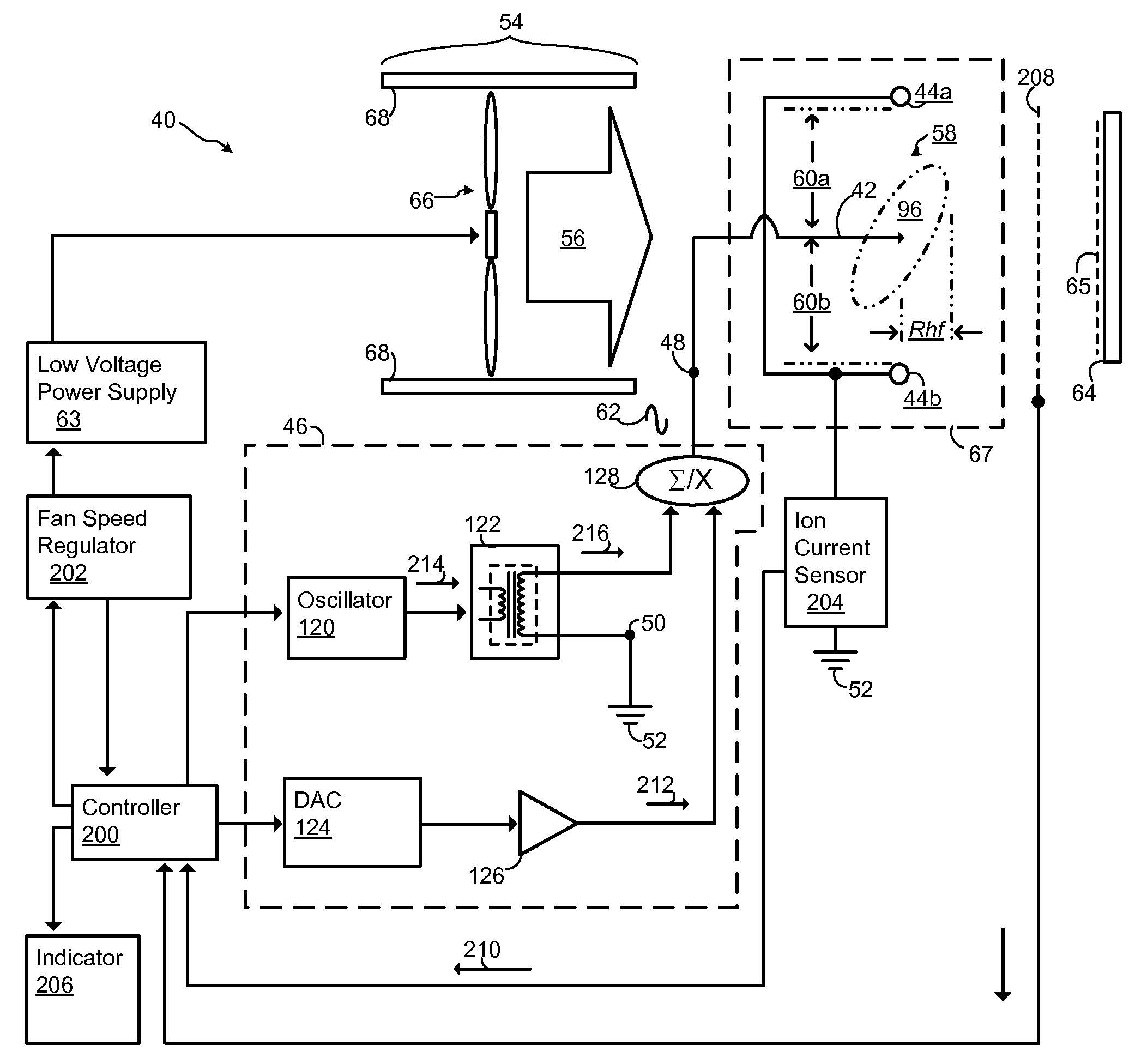
[0032]The present invention establishes a gas flow at a given flow velocity and uses an ionizing voltage waveform that when applied to at least one emitter, helps drive contamination particles away from the emitter(s) and reduces the rate of accumulation of these contamination particles on the emitter(s). When the gas flow passes through a corona discharge region, the gas flow may contain gas borne contamination particles that are affected by the ions generated by corona disch...


PUM


Abstract

A low maintenance AC gas-flow driven static neutralizer, comprising at least one emitter and at least one reference electrode; a power supply having an output electrically coupled to the emitter(s) and a reference terminal electrically coupled to the reference electrode(s) with the power supply disposed to produce an output waveform that creates ions by corona discharge and to produce an electrical field when this output waveform is applied to the emitter(s); a gas flow source disposed to produce a gas flow across a first region that includes these generated ions and the emitter(s), the gas flow including a flow velocity; and wherein, during a first time duration, the output waveform decreases an electrical force created by the electrical field, enabling the gas flow to carry away from the emitter(s) a contamination particle that may be located within a second region surrounding the emitter(s), and to minimize a likelihood of the contamination particle from accumulating on the emitter(s). The first region may include the second region.

Description

CROSS-REFERENCE TO RELATED APPLICATIONS[0001]This application claims the benefit of U.S. Provisional Application having Ser. No. 60 / 918,512, filed 17 Mar. 2007.BACKGROUND OF THE INVENTION[0002]1. Field of the Invention[0003]This invention relates to static neutralizers, sometimes commonly referred to as static-charge neutralizers. More particularly, this invention relates to low maintenance alternating-current (AC) gas flow driven static neutralizers by limiting, preventing or reducing accumulation on their respective emitter(s).[0004]2. Background Art[0005]A static neutralizer is commonly employed to reduce or eliminate electro-static charges that accumulate on or near electro-static sensitive items, such as flat panel displays, electronic circuits, and other items that may be damaged by the discharge of these electro-static charges. To reduce or eliminate these electro-static charges, a static neutralizer creates ions of opposite polarity, which when directed towards an area havin...

Claims


Application Information

Patent Timeline
Patent Type & Authority Applications(United States)
IPC IPC(8): H05F3/00
CPCH01T23/00H05F1/00
Inventor GEFTER, PETERLEVIT, LAWRENCEPARTRIDGE, LESLIEGEHLKE, SCOTT
Owner ILLINOIS TOOL WORKS INC
Why Eureka
Try Eureka