

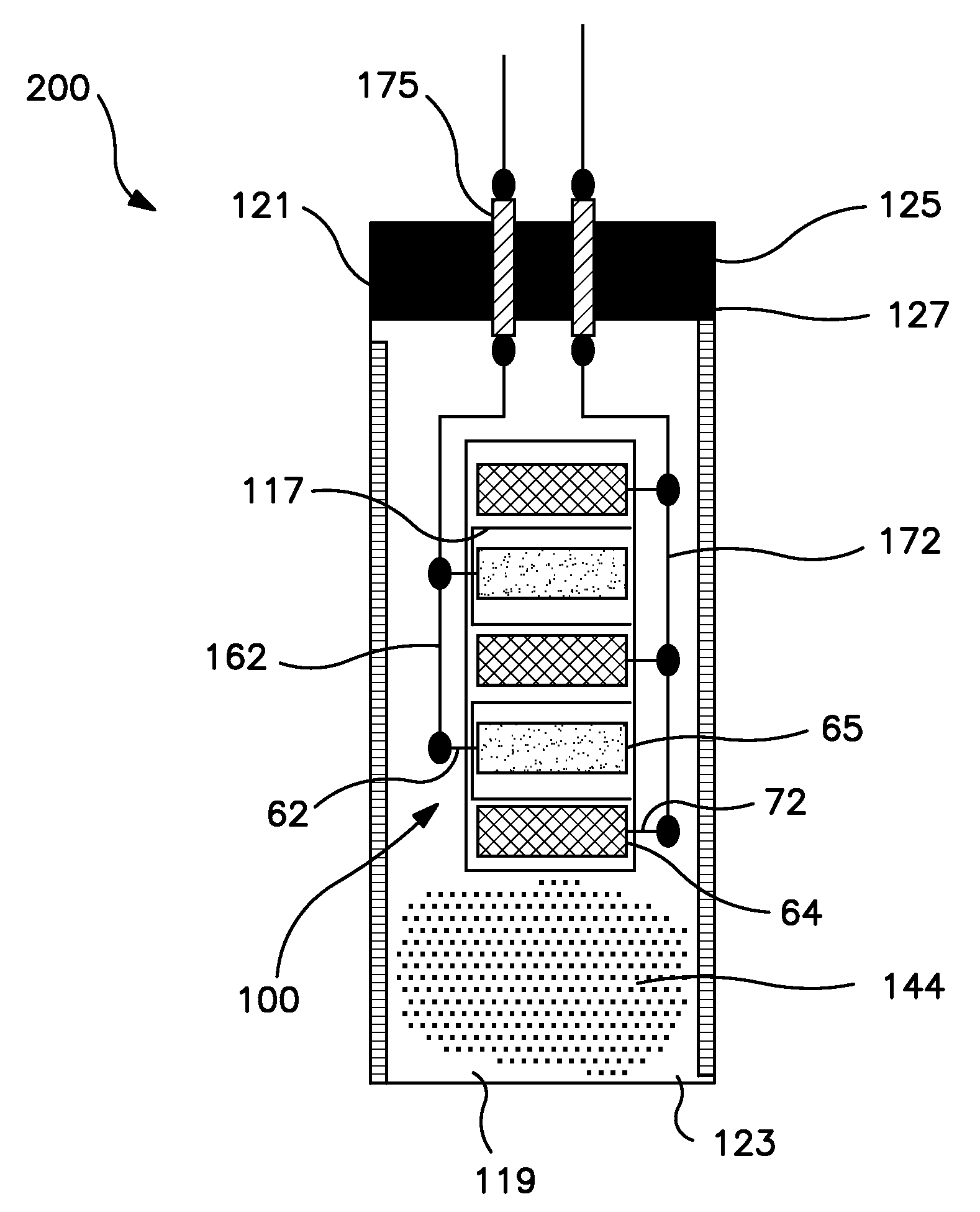
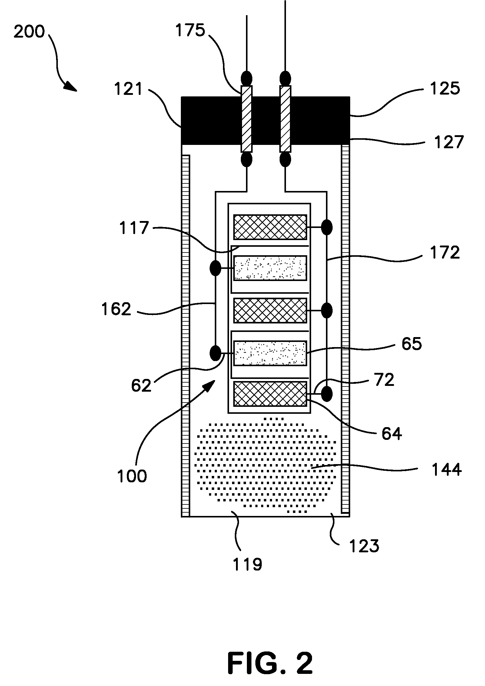
Wet electrolytic capacitor containing a plurality of thin powder-formed anodes
a technology of wet electrolytic capacitors and powder-formed anodes, which is applied in the direction of liquid electrolytic capacitors, casings/cabinets/drawers, electrical apparatus casings/cabinets/drawers, etc., can solve the problem of difficult to incorporate them into applications in which high volumetric efficiency is needed
- Summary
- Abstract
- Description
- Claims
- Application Information
AI Technical Summary
Benefits of technology
Problems solved by technology
Method used
Image

Examples
example 1
[0069]A ceramic body was initially formed from the following composition:
MaterialWt. %DI water19.05Nonionic surfactant0.19Anionic polymer dispersants1.30Acrylic binders9.76Nb2O5 powder69.70
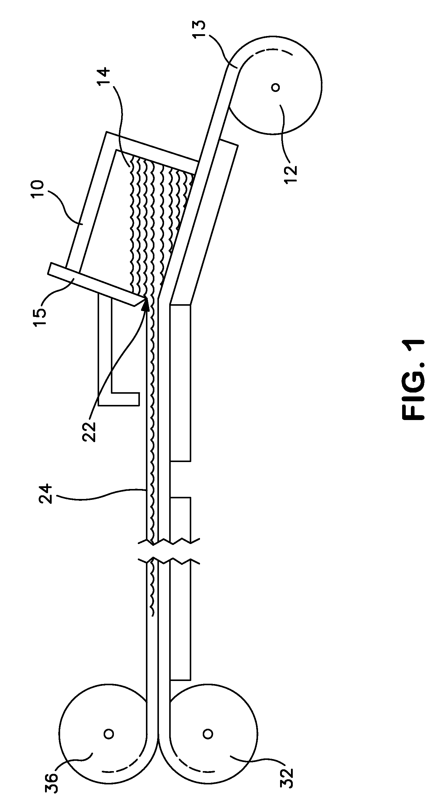
[0070]The ingredients were milled in a dedicated M-18 vibratory mill. Once formed, the composition was de-aired in a slip pot by stirring for 24 hours. The slip was cast into a 0.001875-inch (1.875 mil) tape on a polypropylene carrier. The carrier with the wet tape was floated across a water bath maintained at a constant temperature of 50 C for a period of 2 minutes to facilitate drying. At the end of the drying phase, a metal blade separated the cast tape from the carrier and the tape was rolled together with a single sheet of paper to keep the tape from sticking to itself during storage. 6″×6″ pieces were cut from the tape. 9 of these pieces of tape were then stacked on top of each other and tacked together in a press at 3000 psi for 10 seconds. A sacrificial member was weaved within a loom and ...
example 2
[0071]A wet electrolytic capacitor was formed from the ceramic body of Example 1. Initially, a stainless steel mesh (150×150 mesh, obtained from McMaster) was cut into rectangles of 2.2 cm×1.1 cm. Cathode lead wires (annealed stainless steel 304 wire with a gauge of 150 μm) were cut to a length of 2.5 cm. These rectangles and wires were then rinsed first in 45° C. soap water for 30 minutes in an ultrasonic bath and then rinsed with deionized (“DI”) water 4 times. After drying in an 85° C. oven for 30 minutes, the samples were again degreased in acetone at ambient temperature for 20 minutes. The samples were dried in an 85° C. oven to remove all the residual acetone, rinsed with DI water 5 times and then dried in 85° C. oven. The cathode lead wire was welded to the middle of the 1.1 cm edge of the rectangular mesh using a spot welder. The depth was about 1.0 mm. The rectangular meshes were then etched in a solution of 1.0 vol. % H2SO4 and 0.1 vol. % HCl for 1 minute, degreased with D...
example 3
[0079]A capacitor was formed as described in Example 2, except that carbon black was not employed in the cathode ink. The resulting cathode loading was 0.0107 grams. The measured capacitance at 0.1 Hz was 2.57 mF, 2.42 mF and 2.37 mF for bias of 2.0 V, 5.0 V and 8.0 V, respectively. ESR at frequency of 1000 Hz was 1.98Ω. The cathode capacitance was estimated to be 550.0 mF.
PUM
| Property | Measurement | Unit |
|---|---|---|
| thickness | aaaaa | aaaaa |
| thickness | aaaaa | aaaaa |
| frequency | aaaaa | aaaaa |
Abstract
Description
Claims
Application Information