
Film-Encased Electric Device and Production Method Therefor

Active Publication Date: 2008-09-25
NEC CORP
View PDF5 Cites 22 Cited by
  • Summary
  • Abstract
  • Description
  • Claims
  • Application Information

AI Technical Summary

Benefits of technology

[0015]It is an object of the present invention to provide a film-encased electric device which is capable of easily and reliably setting a released pressure and a pressure releasing position at the time that encasing films are expanded due to the generation of gas in the event of a failure, and a method of manufacturing such a film-encased electric device.
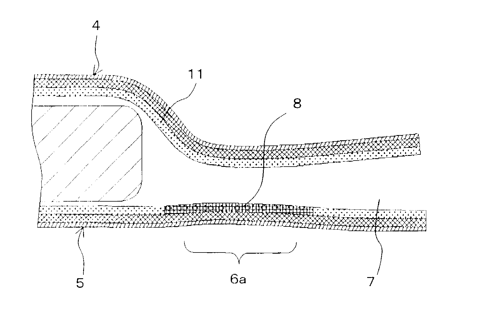
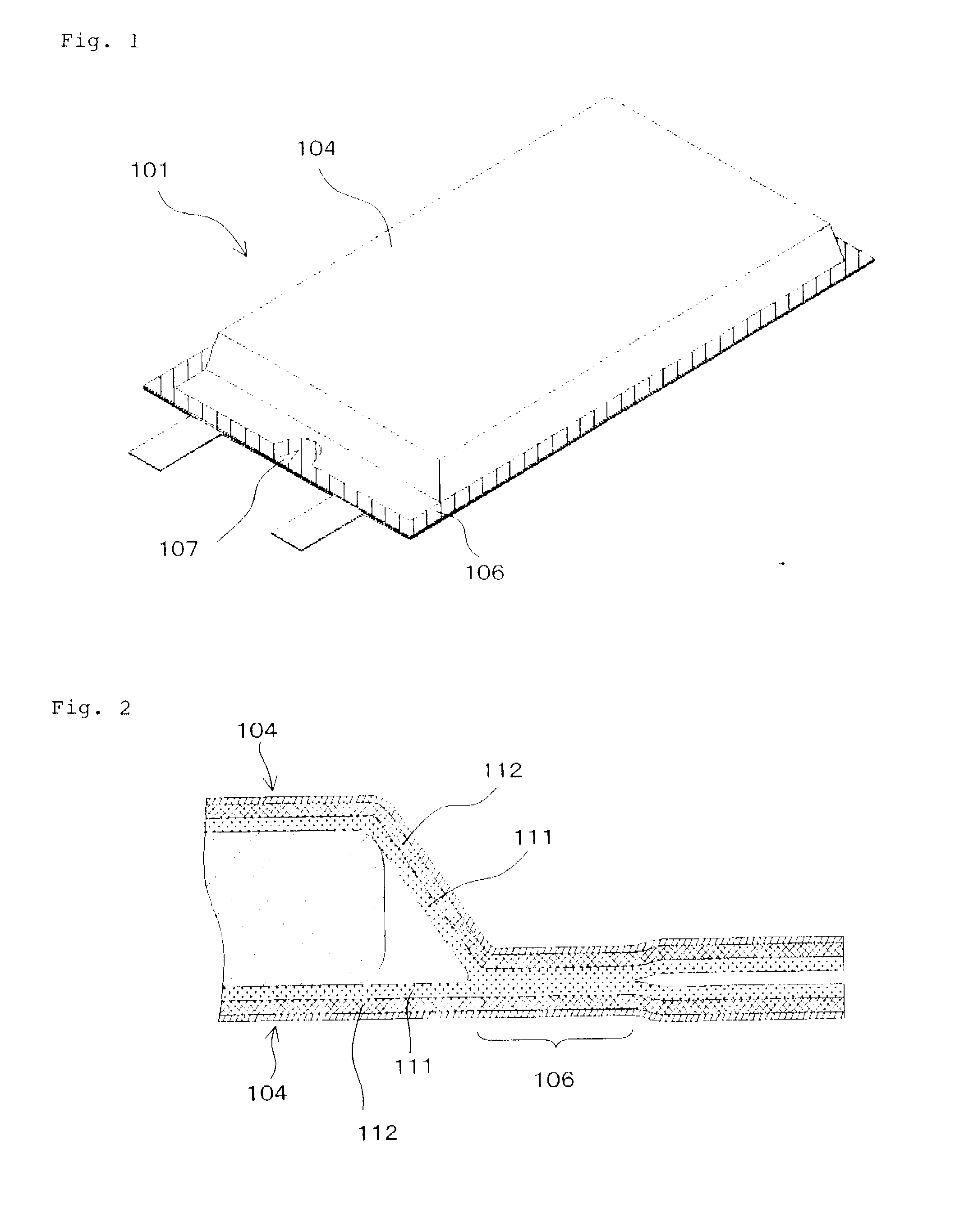
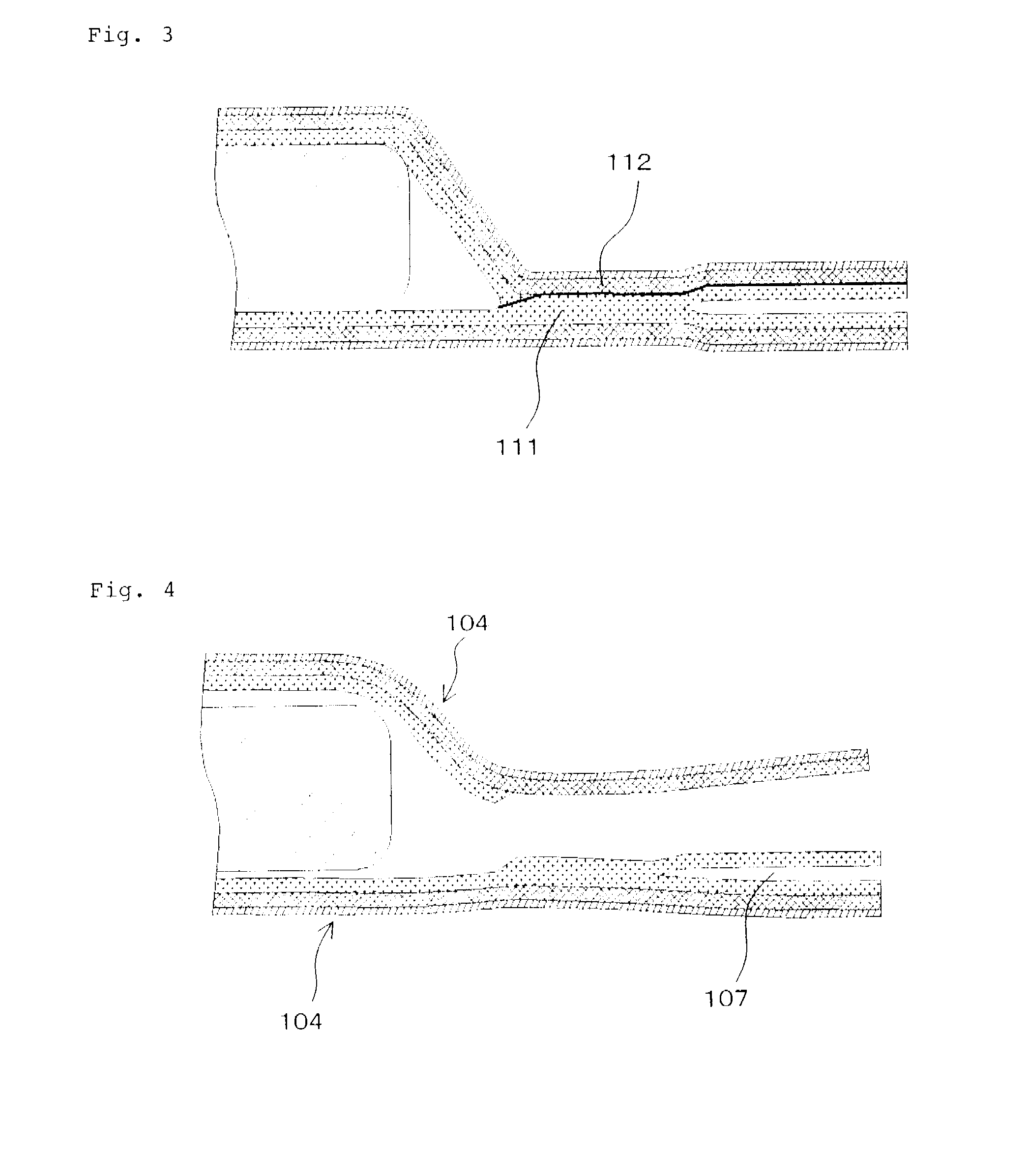
[0017]In the film-encased electric device according to the present invention, the encasing films that face each other have their heat-sealable resin layers thermally fused to each other to seal the electric device element. In the region including the portion of the heat-sealed area, at least one of the encasing films that face each other has the cross-linked structure formed by cross-linking the heat-sealable resin layer in the particular region as described above. When peel-off stress is applied to the heat-sealed area, the encasing films peel off with a smaller force in the region where the cross-linked structure is provided than in other regions. Therefore, when peel-off stress is applied to the heat-sealed area due to internal pressure buildup in the film-encased cell, the encasing films peel off progressively preferentially along the interface between the encasing films that face each other in the region where the cross-linked structure is provided. As a result, a peel-off position and a pressure releasing position are specified, making it easy to configure a released pressure.
[0021]The cross-linked structure may be formed by applying an electron beam to the heat-sealable resin layer. A peel-off force in the region where the cross-linked structure is provided can easily be controlled by the dose of an electron beam applied to form the cross-linked structure.

Problems solved by technology

However, the conventional pressure releasing structure is disadvantageous in that it does not function sufficiently if the encasing films peel off in other regions.

Method used


Image

  • Film-Encased Electric Device and Production Method Therefor
  • Film-Encased Electric Device and Production Method Therefor
  • Film-Encased Electric Device and Production Method Therefor

Examples


first embodiment

[0055]FIG. 5 shows film-encased cell 1 according to the present invention. Film-encased cell 1 has cell element 2 substantially in the 21 form of a flat rectangular parallelepiped having a laminated assembly of positive poles and negative poles, positive pole tab 3a and negative pole tab 3b which are connected respectively to the positive poles and the negative poles of cell element 2, and two encasing films 4, 5 and sealing cell element 2.

[0056]Cell element 2 is of a structure wherein the positive poles and the negative poles, each comprising a metal foil having surfaces that are opposite each other and that are coated with an electrode material, are alternately laminated with separators interposed therebetween. Uncoated portions which are not coated with the electrode material project from respective sides of the positive poles and the negative poles. The uncoated portions of the positive poles are ultrasonically welded together and connected to positive pole tab 3a, and the uncoa...

second embodiment

[0088]In the above embodiment, the single pressure releasing structure is disposed on a shorter side of film-encased cell 1, particularly a side thereof from which positive pole tab 3a and negative pole tab 3b extend. However, the number of pressure releasing structures and the positions where they are located may be changed depending on the purpose for which film-encased cell 1 is used and the conditions in which film-encased cell 1 is used. FIG. 10 shows one example of such a modification as the present invention.

[0089]Film-encased cell 21 shown in FIG. 10 has a pressure releasing structure on a longer side thereof. In the present embodiment, positive pole tab 23a and negative pole tab 23b extend from a shorter side of film-encased cell 21. Therefore, the pressure releasing structure is disposed on a side different from the side from which positive pole tab 23a and negative pole tab 23b extend. A cell element (not shown) is sandwiched and surrounded by two encasing films 24 on bot...

fourth embodiment

[0103]FIG. 13 shows a film-encasing cell according to the present invention. Film-encasing cell 41 according to the present embodiment employs elongate rectangular encasing films 44 having heat-sealed area 46 extending fully therearound and having a constant width, thereby sealing a cell element (not shown). Heat-sealed area 46 includes, in a portion thereof, cross-linked structure 48 disposed in a heat-sealable resin layer and having an inner edge exposed to a cell element housing which accommodates the cell element therein and an outer edge aligned with the outer edge of heat-sealed area 46. Cross-linked structure 48 thus has a portion that, other than the portion that is exposed to the cell element housing, vented to the ambient air.

[0104]Even though no stress concentration area is provided in heat-sealed area 46 according to the present embodiment, the region where cross-linked structure 48 is provided has a smaller peel-off strength than the other region of heat-sealed area 46....


PUM

PropertyMeasurementUnit
Pressureaaaaaaaaaa
Structureaaaaaaaaaa
Areaaaaaaaaaaa

Abstract

A releasing pressure and a pressure releasing position, when enclosing films are expanded by gas produced at an abnormal time, are easily and positively configured. A film-enclosed battery (1) has a battery element (2) and two enclosing films (4, 5) for sealing the battery element (2). The enclosing films (4, 5) include heat-sealable resin layers and air-impermeable layers, and the heat-sealable resin layers and air-impermeable layers, and the heat-sealable resin layers that are face each other hold the battery element (2) and seal the battery element (2) when their peripheral edges are thermally fused. A cross-linking structure (8) formed by cross-linking heat-sealable resin layer is formed in one of the enclosing films (4, 5) so that a region in part of a heat-sealed area (6) has a position exposed to a battery element housing unit and another portion in contact with outside air.

Description

TECHNICAL FIELD[0001]The present invention relates to an electric device typified by a cell or a A capacitor, and more particularly to a film-encased electric device comprising an electric device element such as a chemical cell element, a capacitor element, or the like sealed by an encasing film material, and a method of manufacturing such a film-encased electric device.BACKGROUND ART[0002]One type of film-encased electric device is a film-encased cell. Heretofore, there has been known a film-encased cell including a cell element sandwiched by encasing films placed on respective opposite sides in the thickness direction thereof and having dimensions greater than the planar dimensions of the cell element, the cell element being hermetically sealed (also simply referred to as “sealed”) by the opposite encasing films joined to each other around the cell element. Positive and negative poles tabs are connected as electrodes to the cell element. With the cell element sealed, the tabs exte...

Claims


Application Information

Patent Timeline
IPC IPC(8): H01M2/12B32B37/30H05K7/00H01G9/12H01G11/00H01G11/14H01G11/78H01G11/84H01M50/178H01M50/55H01M50/553H01M50/562H01M50/566
CPCH01G2/08H01G2/103H01G9/08H01G9/12Y02E60/13H01M2/0287H01M2/06H01M2/1229H01G11/80H01M2/021Y02E60/10H01M50/124H01M50/325H01M50/553H01M50/178H01M50/55H01M50/566H01M50/562H01M50/3425H01M50/121H01M50/105H01G11/14H01G11/78H01M50/186H01M50/557H01M50/531
Inventor OTOHATA, MAKIHIROYAGETA, HIROSHI
Owner NEC CORP
Learn More