
Toner for developing electrostatic latent image, and image forming apparatus and process cartridge using the toner

a technology toners, which is applied in the field of toner for developing electrostatic latent images, and image forming apparatus and process cartridges using toners, can solve the problems of deterioration of microscopic dot reproducibility, difficult to clean stably a toner having a small and uniform particle diameter, and difficult to produce high-quality images stably, etc., to achieve good microscopic dot reproducibility and high cleanability. s

Active Publication Date: 2008-09-25
RICOH KK
View PDF44 Cites 28 Cited by
  • Summary
  • Abstract
  • Description
  • Claims
  • Application Information

AI Technical Summary

Benefits of technology

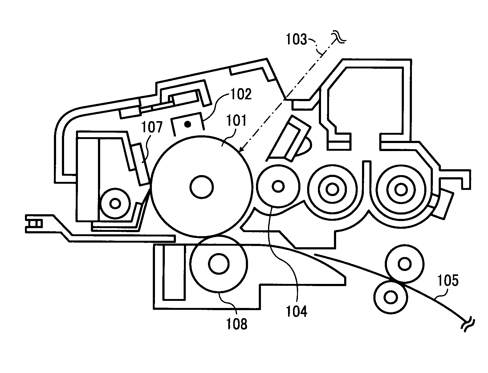
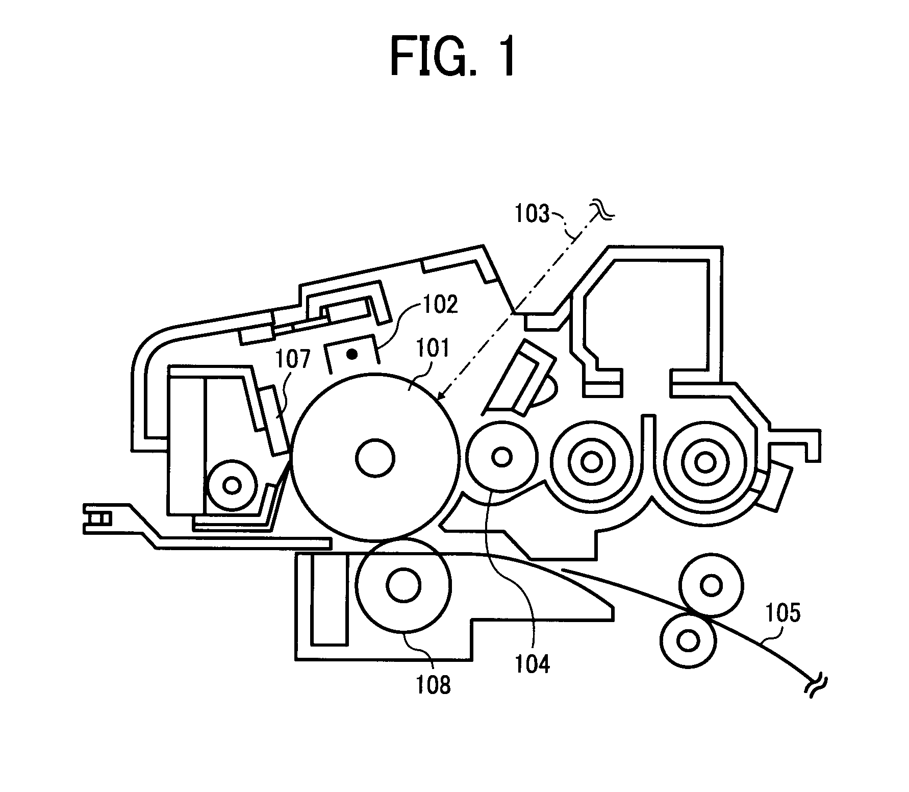
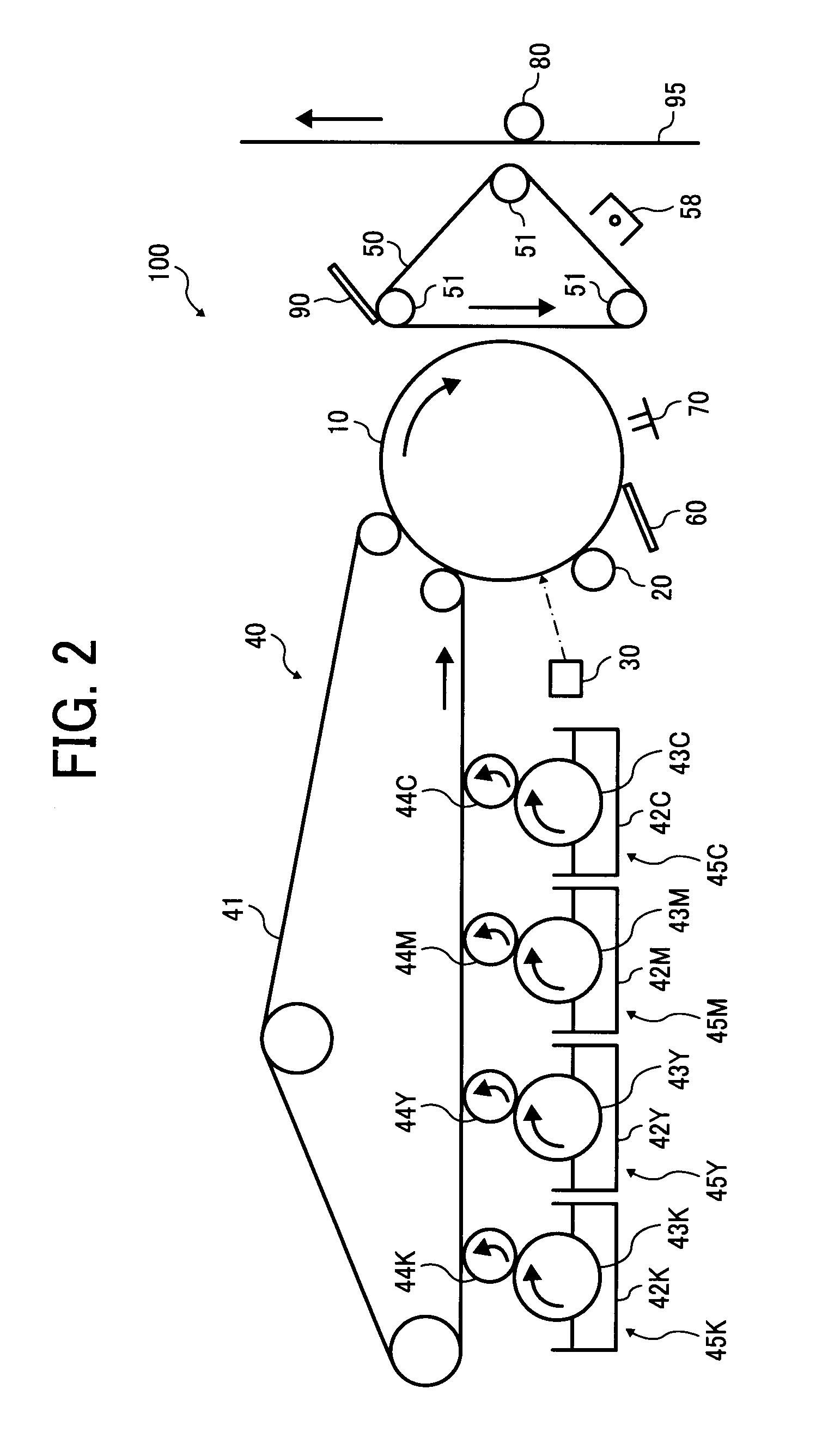
The present invention provides a toner for developing electrostatic latent images that has high cleanability, transferability with less untransferred toner, and filming resistance. The toner can stably produce high-quality images even at high temperatures and / or humidity. An image forming apparatus and a process cartridge using this toner are also provided. The toner is prepared at low cost and high yield. The toner comprises a parent particulate material, a colorant, and a binder resin, and an external additive comprising particles having different average primary particle diameters. The particles having an average primary particle diameter not less than 800 and not greater than 1500 nm are heated at a temperature of -30 to +250°C and have a weight reduction rate not greater than 3.00%.

Problems solved by technology

However, it has conventionally been difficult to stably clean a toner having a small and uniform particle diameter, and particularly a blade cleaner is very difficult to clean the toner having a small and uniform particle diameter.
However, when the shape of a toner is too irregular, the toner irregularly behaves, resulting in deterioration of microscopic dot reproducibility.
As mentioned above, although the toner having an irregular shape has reliable cleanability, the toner is difficult to transfer.
Although the toner initially has high transferability and cleanability, the external additives are easily buried or peeled, resulting in large deterioration of the transferability and cleanability.
Having a large specific gravity, the inorganic particulate material having a large particle diameter does not adhere well to a toner and easily leaves therefrom, resulting in longer life of a cleaning blade.
Japanese published unexamined application No. 2001-66820 discloses the inorganic particulate material having a large particle diameter and an order of adding an external additive, but does not balance between forming the dam and preventing the filming.
Japanese published unexamined application No. 2001-13837 discloses a method of forming the dam, but needs an exclusive external additive applicator and is difficult to save space and cost.
In addition, it is inconvenient that the external additive needs to be exchanged separately.
However, the external additive having a particle diameter of from 0.080 to 0.500 μm, which is likely to leave from the toner, is not mentioned and an action against the filming over a photoreceptor is not fully performed.

Method used


Image

  • Toner for developing electrostatic latent image, and image forming apparatus and process cartridge using the toner
  • Toner for developing electrostatic latent image, and image forming apparatus and process cartridge using the toner
  • Toner for developing electrostatic latent image, and image forming apparatus and process cartridge using the toner

Examples


example 1

[0271]0.6 parts of the external additive (A) and 0.7 parts of the external additive (C) were mixed with 100 parts of the parent toner particles by a Henschel Mixer Mitsui Mining Co., Ltd. at a peripheral speed of 33 m / s for 3 min, and 0.5 parts of the external additive (G) was further mixed therewith at a peripheral speed of 33 m / s for 3 min to prepare a powder. The powder was passed through a mesh having an opening of 38 μm to remove coarse particles. Thus, a toner A onto which hydrophobic fine powders were externally added was prepared.

example 2

[0272]0.6 parts of the external additive (A) and 0.7 parts of the external additive (D) were mixed with 100 parts of the parent toner particles by a Henschel Mixer Mitsui Mining Co., Ltd. at a peripheral speed of 33 m / s for 3 min, and 1.2 parts of the external additive (H) was further mixed therewith at a peripheral speed of 33 m / s for 3 min to prepare a powder. The powder was passed through a mesh having an opening of 38 μm to remove coarse particles. Thus, a toner B onto which hydrophobic fine powders were externally added was prepared.

example 3

[0273]0.6 parts of the external additive (A) and 0.7 parts of the external additive (C) were mixed with 100 parts of the parent toner particles by a Henschel Mixer Mitsui Mining Co., Ltd. at a peripheral speed of 33 m / s for 3 min, and 1.2 parts of the external additive (G) was further mixed therewith at a peripheral speed of 33 m / s for 3 min to prepare a powder. The powder was passed through a mesh having an opening of 38 μm to remove coarse particles. Thus, a toner C onto which hydrophobic fine powders were externally added was prepared.


PUM

PropertyMeasurementUnit
average primary particle diameteraaaaaaaaaa

Abstract

A toner, including a parent particulate material including a colorant and a binder resin, and an external additive including particles having an average primary particle diameter from 80 to less than 150 nm in an amount of from 0.03 to 2% by number, particles having an average primary particle diameter from 5 nm to less than 15 nm in an amount of from 50 to 95% by number, and particles having an average primary particle diameter from 15 to less than 40 nm in an amount of from 5 to 40% by number, and the particles having an average primary particle diameter from 80 to less than 150 nm include particles having an average primary particle diameter not less than 200 nm in an amount of from 10 to 30% by number, and have a weight reduction rate not greater than 3.00% when heated from 30 to 250° C.

Description

BACKGROUND OF THE INVENTION[0001]1. Field of the Invention[0002]The present invention relates to a toner for use in a developer for developing an electrostatic latent image in electrophotography, electrostatic recording, electrostatic printing, etc., and to an image forming apparatus and a process cartridge using the toner. More particularly to a toner for developing an electrostatic image for use in copiers, laser printers, plain paper facsimiles, etc. using direct or indirect electrophotographic developing method, an image forming apparatus and a process cartridge using the toner, and to a method of preparing the toner.[0003]2. Discussion of the Background[0004]Recent strong demands for higher quality images from the market spur development of suitable image forming apparatuses and a developer (toner) for use therein.[0005]The toner for higher quality images needs to have a uniform particle diameter. This is because when a toner having a sharp particle diameter distribution, indiv...

Claims


Application Information

Patent Timeline
Patent Type & Authority Applications(United States)
IPC IPC(8): G03G9/08G03G15/06
CPCG03G9/0806G03G9/0819G03G9/08795G03G9/09725G03G9/0904G03G9/09716G03G9/08797
Inventor NAGATOMO, TSUNEYASUWATANABE, NAOHIROUCHINOKURA, OSAMUKOJIMA, SATOSHI
Owner RICOH KK
Learn More