System For Guiding a Medical Instrument in a Patient Body

a technology for guiding a medical instrument and a patient body, applied in the field of medical systems, can solve the problems of low resolution, complicating the interventional procedure, narrow viewing field, etc., and achieve the effect of improving the visibility of the medical instrument and its surrounding anatomy

Inactive Publication Date: 2008-09-25
KONINKLIJKE PHILIPS ELECTRONICS NV
View PDF4 Cites 28 Cited by
  • Summary
  • Abstract
  • Description
  • Claims
  • Application Information

AI Technical Summary

Benefits of technology

[0007]The object of the invention is therefore to provide a system for guiding a medical instrument in a patient body, which gives an improved visibility of the medical instrument and its surrounding anatomy during the whole procedure.

Problems solved by technology

A first drawback of such a 3D ultrasound data set is to have a narrow viewing field, which does not cover the whole part of the patient body concerned by a catheter introduction and placement.
Such a pre-operative step may delay and complicate the interventional procedure.
A second drawback of the ultrasound imaging modality is to have a low resolution Therefore, the acquired 3D ultrasound data set does not give an image of the catheter and its surrounding of acceptable quality.
A third drawback of the ultrasound imaging modality is that there are some zones of the patient body where the thoracic cage blocks the ultrasound scan and no exploitable image can be output.

Method used


Image

  • System For Guiding a Medical Instrument in a Patient Body
  • System For Guiding a Medical Instrument in a Patient Body
  • System For Guiding a Medical Instrument in a Patient Body

Examples


first embodiment

[0066]In an alternative of the invention, the whole tip is detected, which allows to determine a location of a landmark, for instance the tip end T and an orientation of the tip, specified by two Euler angles. Advantageously, a transformation comprising a translation and two rotations can be derived and the mapping of the 3D ultrasound data set with the 2D X-Ray image is improved.

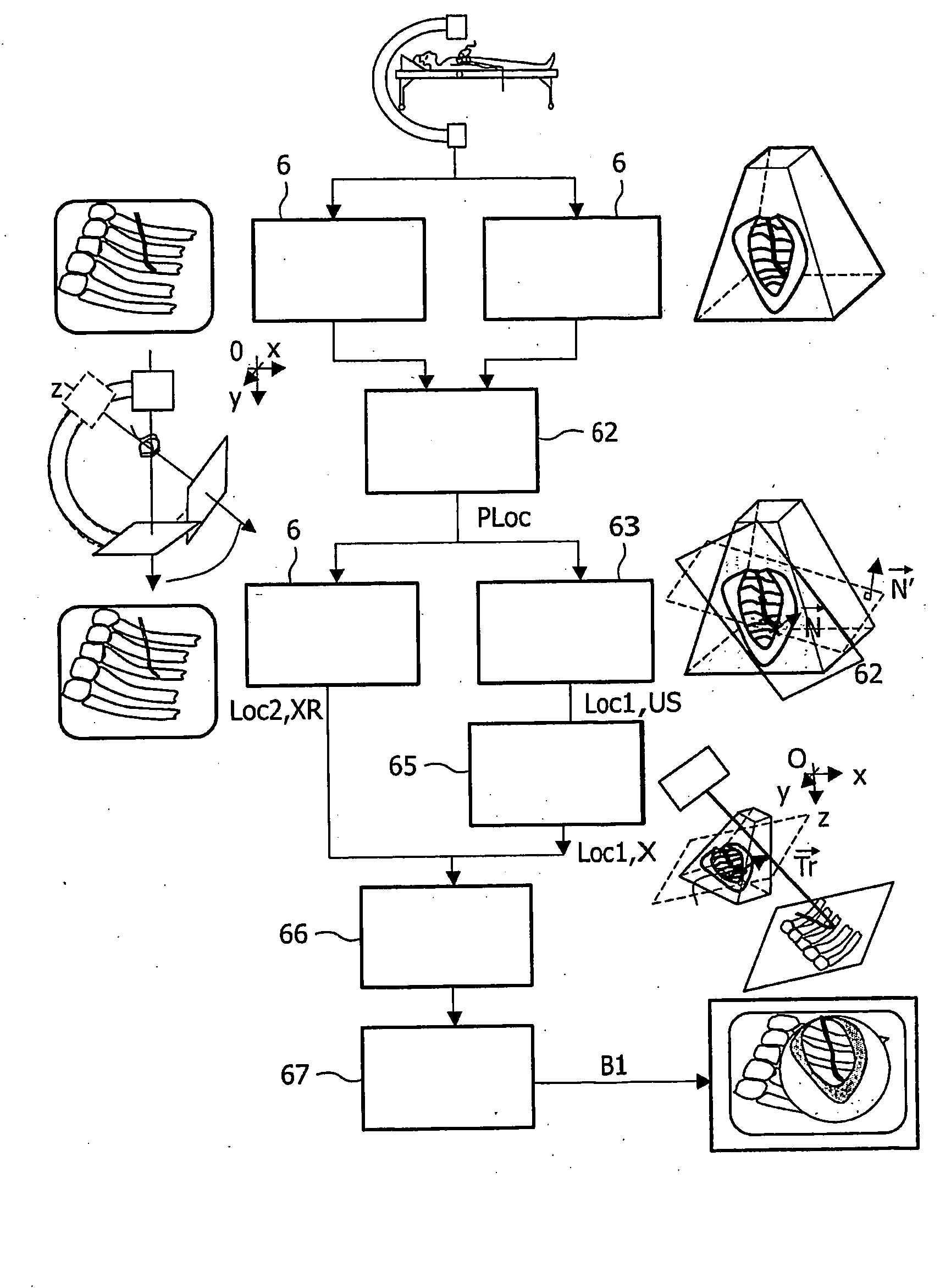
[0067]In a second embodiment of the invention also illustrated by FIG. 5, the first and second localizations of the medical instrument 4 are based on the detection of a plurality, i.e. at least three non aligned landmarks T, Lk2, Lk3, which are arranged on the medical instrument 4. Such a plurality of landmarks allow to define a second crop plane 33 and a second normal {right arrow over (N)}′ within the 3D ultrasound data set, which can advantageously serve for reorienting the X-ray source 6 in order to optimize the X-ray acquisition with respect to the detected position of the medical instrument 4. An adva...

third embodiment

[0068]In the invention illustrated by FIG. 8, the plurality of landmarks are distributed over the medical instrument 4 and at least two reference medical instruments 40, 41. Said reference medical instruments 40, 41 are both fixed in the patient body during the whole clinical procedure and comprise each an echogen and radioopaque tip T2, T3. They may also comprise other landmarks than the tips T, T2, T3, which may allow for instance the determination of tip orientations {right arrow over (O)}1, {right arrow over (O)}2, {right arrow over (O)}3.

[0069]A first advantage of the third embodiment of the invention is that the landmarks used for localizing the medical instrument are more distant from each other. Therefore, the definition of the transformation is more robust to local errors of localization. As a matter of fact an error of one or two pixels has no consequences at a vicinity of the medical instrument, but can have dramatical effects in more distant areas of the 3D ultrasound da...

second embodiment

[0080]Another possibility is to use an active contour technique (also called “snake”). This technique, well known to those skilled in the art, firstly consists in defining an initial contour and secondly in making said initial contour evolve under the influence of internal and external forces. A final contour 46 is obtained. It is then possible to differentiate points located inside from points located outside the contour 46 and to replace only the outside points of the 2D X-ray projection 40 by the corresponding points of the 2D ultrasound view 41. An advantage of this second embodiment is to benefit from X-ray information in a larger neighbourhood of the medical instrument 4.

[0081]In another alternative of the invention, an alpha blending technique, well-known to those skilled in the art, is used for combining the X-ray intensity values of the points of the X-ray projection with the ultrasound intensity values of the corresponding points of the 3D ultrasound data set. An advantage...


PUM


Abstract

The present invention relates to a medical system comprising a medical instrument to be guided in a patient body, ultrasound acquisition means using an ultrasound probe for acquiring a 3D ultrasound data set and X-ray acquisition means for acquiring a 2D X-Ray image, which comprises a projection of said medical instrument. The system in accordance with the invention further comprises means for localizing said ultrasound probe within a referential of said X-Ray acquisition means, means for providing a first localization of said medical instrument within a referential of the ultrasound acquisition means, means for converting said first ultrasound localization into a first X-Ray localization within the referential of said X-Ray acquisition means, means for providing a second X-Ray localization of the projection of said medical instrument in the two-dimensional X-ray image, means for mapping said 3D ultrasound data set with said 2D X-ray image in accordance with a transformation, which minimizes a distance between a projection of said first X-Ray localization on said 2D X-Ray image and said second X-Ray localization and means for generating and displaying a bi-modal representation of said medical instrument, in which said 2D X-ray image and said mapped 3D ultrasound data are combined.

Description

FIELD OF THE INVENTION[0001]The present invention relates to a medical system. The invention also relates to a method to be used in said system. The invention finds for example its application for guiding a catheter inside the heart of a patient during an electrophysiology interventional procedure.BACKGROUND OF THE INVENTION[0002]Clinical applications in which a medical instrument has to be guided into the body of a patient are becoming widespread. Notably the growing interest in minimal-invasive methods for the treatment of cardiac diseases necessitates the development of methods and devices allowing the physician to guide a medical instrument to predetermined positions inside or outside the heart. In electrophysiology for example, it is necessary to guide a catheter to a plurality of predetermined positions on the ventricular or atrial walls in order to measure an electrical pulse or to burn wall tissues.[0003]U.S. Pat. No. 6,587,709 discloses a system for guiding a medical instru...

Claims


Application Information

Patent Timeline
Patent Type & Authority Applications(United States)
IPC IPC(8): A61B6/12A61B8/08A61B19/00
CPCA61B6/12A61B6/5247A61B8/0833A61B2019/5289A61B8/5238A61B2019/5238A61B2019/5276A61B8/4245A61B2090/364A61B2090/376A61B2090/378
Inventor GERARD, OLIVIERFLORENT, RAOUL
Owner KONINKLIJKE PHILIPS ELECTRONICS NV
Why Eureka
Try Eureka