Tool and a Method for Attaching a Cardiac Stimulator Lead at a Desired Position Inside a Heart

a technology of cardiac stimulator and tool, which is applied in the direction of external electrodes, ear treatment, diagnostics, etc., to achieve the effect of limiting the torque transmitted, simple, inexpensive and reliabl

Inactive Publication Date: 2008-09-25
ST JUDE MEDICAL
View PDF2 Cites 18 Cited by
  • Summary
  • Abstract
  • Description
  • Claims
  • Application Information

AI Technical Summary

Benefits of technology

[0009]It is an object of the invention to eliminate at least some of the above disadvantages and provide a simple, inexpensive and reliable tool for limiting the torque transmitted to the helix when attaching a cardiac stimulator lead to a heart wall.
[0010]Accordingly, the basis of the invention is the insight that there is a need for a torque limiter, which prevents further rotating of the helix when a sufficient length has been screwed out from the tip, and which prevents twisting of the entire lead. However, such a torque limiter should preferably be as inexpensive and uncomplicated as possible, and yet ensure a reliable function, especially since the torque limiter normally will be disposed of after use.
[0018]When rotating the helix by means of the torsion wire, it is important to press the torsion wire towards the distal end such that proper engagement is ensured between the distal end of the torsion wire and the proximal end of the operating member. It may also be necessary to press the torsion wire towards the distal end to ensure proper abutment of the end of the tip in the cardiac stimulator lead against the heart wall. However, to prevent too much pressure in the longitudinal direction of the torsion wire it is preferred, according to one embodiment of the invention, to support the portion of the torsion wire located in the handle on the distal side of the internal cavity, not only rotatable but also displaceable in the longitudinal direction. In this way is in a simple manner achieved, due to the elastic yoke, a pressure limiter which resilient restrains the maximal longitudinal pressure force in the torsion wire.
[0019]In a further preferred embodiment, the tool is especially adapted for the case where the cardiac stimulator lead is guided by means of an elastic guide tube having a curved distal portion, which is inserted into the cardiac stimulator lead and used for pivoting the tip of the cardiac stimulator lead to the desired position by rotating the guide tube at the proximal end. For this reason the handle is divided into two parts, namely a first and a second handle piece, respectively, which are rotatable connected to each other, the first handle piece forming the distal end of the internal cavity, whereas the second handle piece forming the circumferential boundary surface and the proximal end of the internal cavity. In this embodiment the proximal end of the guide tube is torsion resistant connected to the first handle piece, in coaxial with the centre axis of the cavity and on the distal side of the internal cavity. The torsion wire is inserted into the guide tube, has a yoke portion within the internal cavity and is rotationally supported by the second handle piece in coaxial with the centre axis of the internal cavity and in the proximal end thereof. The torsion wire is rotatable and displaceable supported in the guide tube. A tool designed in this way will have the same advantages as described earlier in relation to the torsion wire, i.e. when rotating the second handle piece in relation to the first handle piece, the torsion wire will function as a torque limiter, by engagement of the yoke in the grooves and ridges of the internal cavity, when rotated for extending the helix from the tip of the cardiac stimulator lead and hence attaching it to the heart wall. The torsion wire will also function as a pressure limiter by being displaceable in the longitudinal direction due to deformation of the elastic yoke. A further advantage with this tool is that by rotating of the first handle piece in relation to the second handle piece, the tip of the cardiac stimulator lead can be pivoted and hence guided to the desired position inside the heart. When the tip is located in the desired location, it can be hold in position by means of the first handle piece while the helix being screwed out from the tip by rotating the second handle piece.

Problems solved by technology

However, such a torque limiter should preferably be as inexpensive and uncomplicated as possible, and yet ensure a reliable function, especially since the torque limiter normally will be disposed of after use.

Method used


Image

  • Tool and a Method for Attaching a Cardiac Stimulator Lead at a Desired Position Inside a Heart
  • Tool and a Method for Attaching a Cardiac Stimulator Lead at a Desired Position Inside a Heart
  • Tool and a Method for Attaching a Cardiac Stimulator Lead at a Desired Position Inside a Heart

Examples


first embodiment

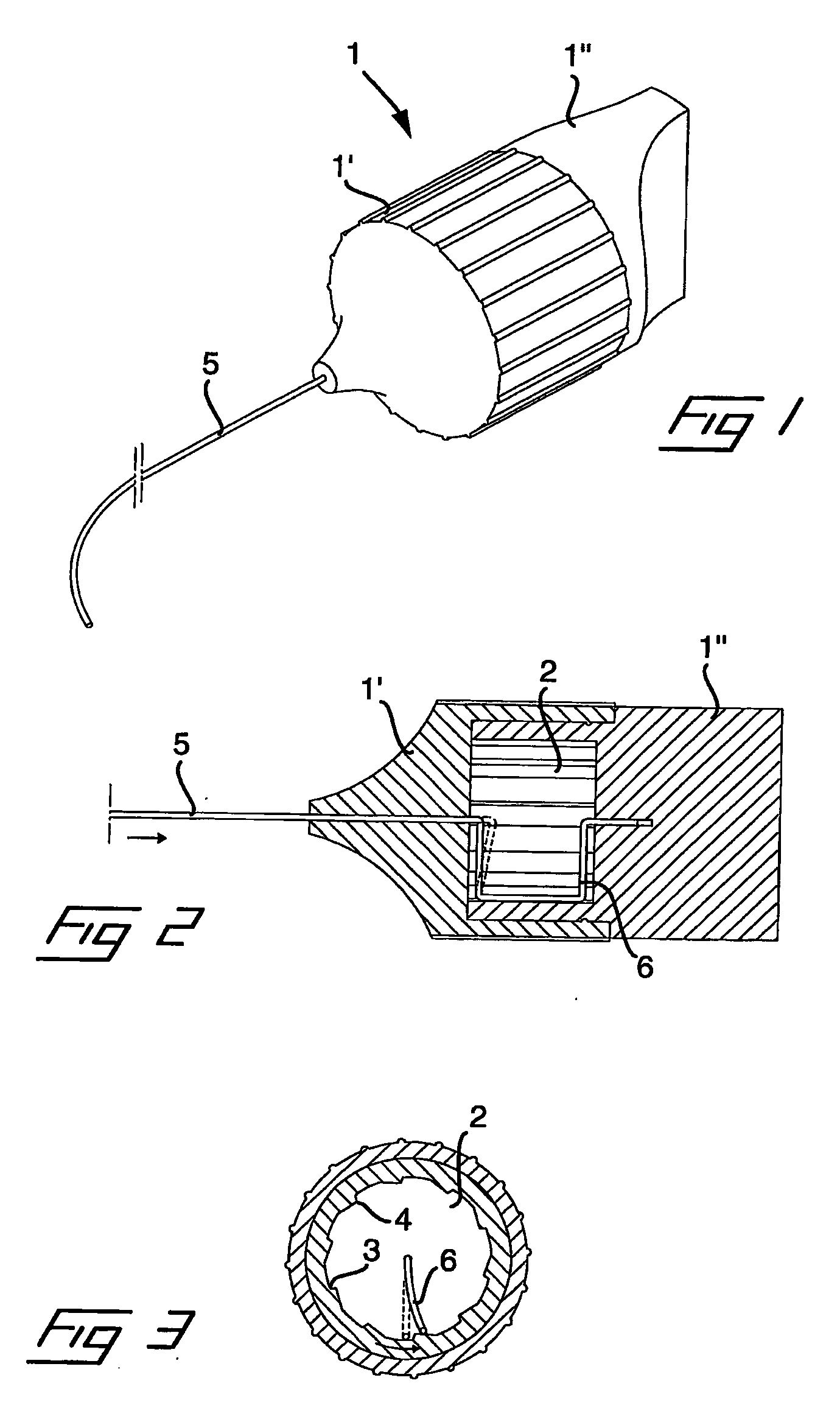
[0029]Reference is first made to FIGS. 1 and 2 in which a tool according to the invention is illustrated in a perspective view and a longitudinal section, respectively. The tool comprises a handle 1 of a general cylindrical shape. The handle is assembled of a first handle piece 1′ and a second handle piece 1″, wherein a portion of the second handle piece is inserted into the first handle piece. A cylindrical recess is provided in the second handle piece, such that in an assembled state, the two handle pieces will define an internal cavity 2. The cavity has a general circular cross section, as is seen from FIG. 3, but is provided with grooves 3 and ridges 4 in the longitudinal direction of the envelope surface or circumferential boundary surface of the cylindrical cavity.

[0030]A bore is provided in the first handle piece 1′, which is forming the distal end or side of the cavity, as well as in the second handle piece 1″, which is forming the proximal end or side of the cavity. Both of...

second embodiment

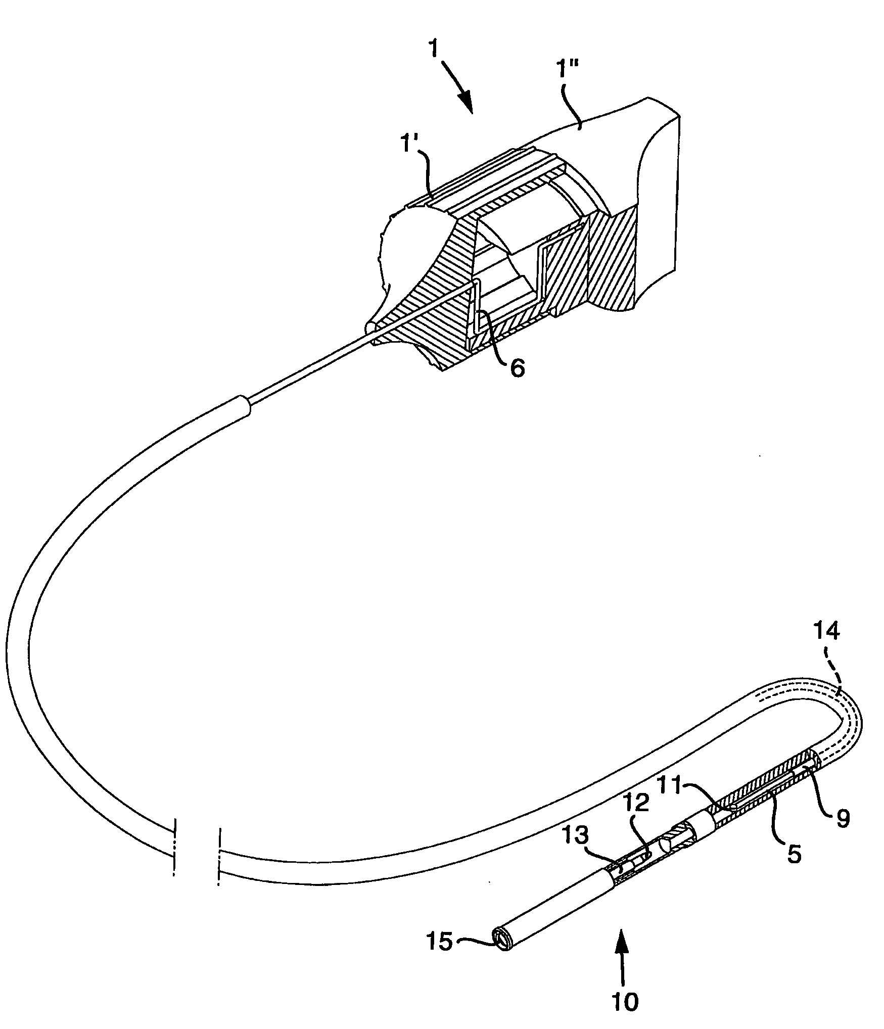
[0036]Referring now to FIG. 8 in which is shown a partly cut through perspective view of a complete tool, according to the invention. In the drawing is indicated the use of the tool for guiding and attaching of a cardiac stimulator leadhaving a tip 10 in its distal end. In reality, the cardiac stimulator has nearly the same length as the torsion wire 5 and the guide tube 9 of the tool, and is preferably inserted through a vein, e.g. in the area of a patient's shoulder, and pushed through the vein until the tip 10 is located inside the heart. When the tip is inside the heart, the torsion wire 5 and the guide tube 9 is inserted into a bore, which is provided in the cardiac stimulator lead, until the torsion wire and the guide tube is in the area of the tip 10. As is indicated in the drawing, the distal end of the torsion wire is provided with an engagement formation 11 which is adapted to engage a mating engagement formation 12 in a proximal end of an operating member 13 in the tip 10...


PUM


Abstract

For attaching a cardiac stimulator lead at a desired position inside a heart, the stimulator lead having a flexible tube from which a helix is extendible at a distal end thereof by a screw rotating motion and having a proximal end interconnected with an operating member, a tool has a flexible portion wire with an engagement formation at a distal end thereof that mates with a complimentary engagement formation at a proximal end of the operating member. The tool has a handle containing an internal cavity, with a proximal portion of the torsion wire being rotationally rotated by the handle in the internal cavity, and a resilient yoke is formed in the internal cavity, with at least a part of the yoke engaging grooves and ridges in a circumferential boundary surface of the internal cavity.

Description

FIELD OF THE INVENTION[0001]The present invention relates to a tool for attaching a cardiac stimulator lead at a desired position inside a heart, the stimulator lead being of the type which is formed as a flexible tube comprising electrical conductors and a helix, which is extendable out of a distal end of the tube by a screw rotating motion, for penetration into and hence attachment at the desired position, and which, in its proximal end, is interconnected with an operating member, the tool comprising a flexible torsion wire, having an engagement formation in a distal end, and being insertable into the cardiac stimulator lead, to effect the screw rotating motion of the operating member by rotating the torsion wire when the engagement formation in the distal end of the torsion wire is in engagement with a mating engagement formation in a proximal end of the operating member.[0002]The invention also relates to a method for attaching of such a cardiac stimulator lead at a desired posi...

Claims


Application Information

Patent Timeline
Patent Type & Authority Applications(United States)
IPC IPC(8): A61N1/05A61M5/00
CPCA61N2001/058A61N1/0573
Inventor STEGFELDT, OLOFHILL, ROLF
Owner ST JUDE MEDICAL
Why Eureka
Try Eureka