
Generation Facility Management System

a technology of management system and generation facility, applied in the direction of wind energy generation, natural sources for heating, electric devices, etc., can solve the problems of increasing load factor, electric power, deterioration year by year, etc., and achieve the effect of raising consciousness of energy saving and energy creation, and promoting the introduction of generation facilities using natural energy

Inactive Publication Date: 2008-09-25
SHARP KK
View PDF7 Cites 34 Cited by
  • Summary
  • Abstract
  • Description
  • Claims
  • Application Information

AI Technical Summary

Benefits of technology

[0027]According to the present invention, a consideration is given to the generation facility with small environmental load whose value is not conventionally clear or to the power generated by using natural energy. Therefore, a preferred profit is given to both of a subscriber who possesses the aforementioned generation facilities and a trader (value acquisition intender) who acknowledges the value in such a self-generation and gives the consideration thereto, and thus the introduction of the generation facility using natural energy can be promoted.

Problems solved by technology

When power demand is paid more attention to, along with an improvement in convenience of various OA machineries, air conditioner facilities, and other household appliance articles, power consumption has been rising year by year, and further a load factor, which is a ratio of electric energy of a peak hour to an average electric power, has been deteriorated year by year.
A deterioration of load factor involves a problem that a power company is required to maintain the generation facility for responding to peak power, and the generation facility cannot be effectively used.

Method used


Image

  • Generation Facility Management System
  • Generation Facility Management System
  • Generation Facility Management System

Examples


embodiment 1

[0198]Next, an explanation will be given to a specific example of an embodiment wherein the subscriber selects any one of the considerations out of a plurality of considerations. Here, the following information is assumed to be previously stored in the information storage section of the management server 400.

Information Stored in Value Acquisition Intender Information Database 404

(1) Provider: The Trader B Who Manufactures and Sells Camping Equipment.

[0199]Condition: Support situation should be printed in a home page of environmental contribution.

[0200]Consideration: Free tableware set for camping is provided to self power consumption of 1000 kWh out of the self power generation.

[0201]Acquisition request power quantity: 30000 kWh (The first 30 people).

(2) Provider: Trader C Who Sells Flower Arrangement by Home Delivery.

[0202]Condition: Support situation should be printed in a home page of environmental contribution.

[0203]Consideration: When the self power consumption out of the self...

embodiment 2

[0216]Next, an explanation will be given to a specific example of acquiring the value and consideration defined by this application, by investing in the facility of the third person. It is assumed that there is a case of a plan to setting up 100 illumination machineries having the photovoltaic generation and a battery disposed side by side therein, in a main street reaching in the city hall of S-city. The illumination machinery accumulates the power generated in the daytime in a battery, and turns on the illumination in the night. The mechanism is that in case that the battery is fully charged when fine weather continues, a reverse power flow is performed to a system, and the power is sold. Further, the management system of the present invention is mounted on a street light, which is capable of performing a centralized management of 100 illumination machineries.

[0217]In setting up the street light, an expense required for setting up the street light of conventional type, and electri...

embodiment 3

[0223]

[0224]Frequent flier programs and article acquisition by point system, and systems of conversion in cash that aimed at enclosure of a user, are spread in a card company, an airline, and various kinds of stores. A specific example of a mutual service with such a service will be explained. In this case, it is necessary to handle the power quantity as a common unit by converting the power quantity obtained by the power information into points, etc, based on each value information. The mutual service with a card company will be explained hereafter.

Power value 1 kWh=1 point

Amount of card use of J company 1 point per 10,000 yen

[0225]The information on a subscriber Z in a case of holding the photovoltaic generation system of 3 kW and paying purchase expense 2,000,000 yen of a new car by using a card of J company, is as follows.

(Z-1) Particular Information on the Subscriber Z: Name, Address, ID Number, and Telephone Number

(Z-2) Consideration Contract Information: Unknown

(Z-3) Current ...


PUM


Abstract

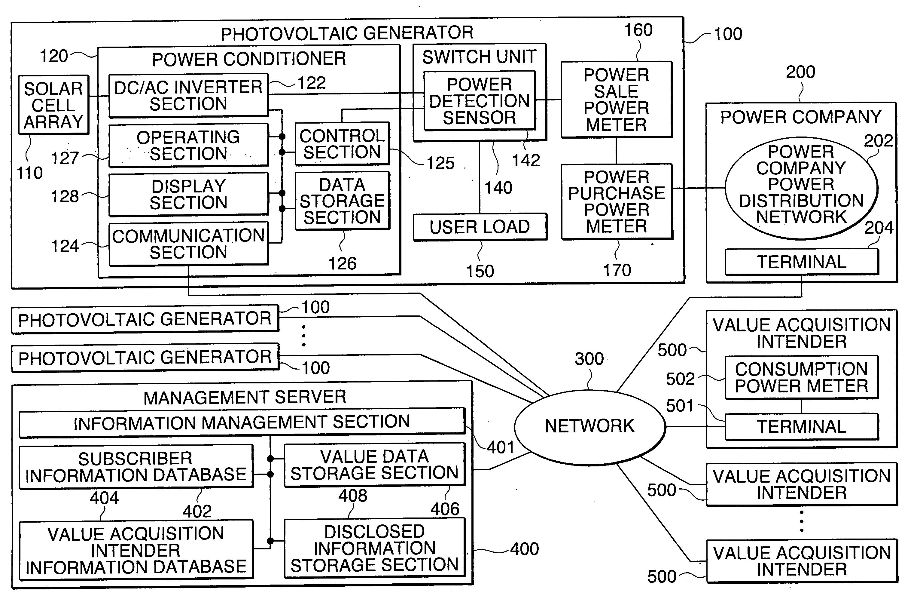
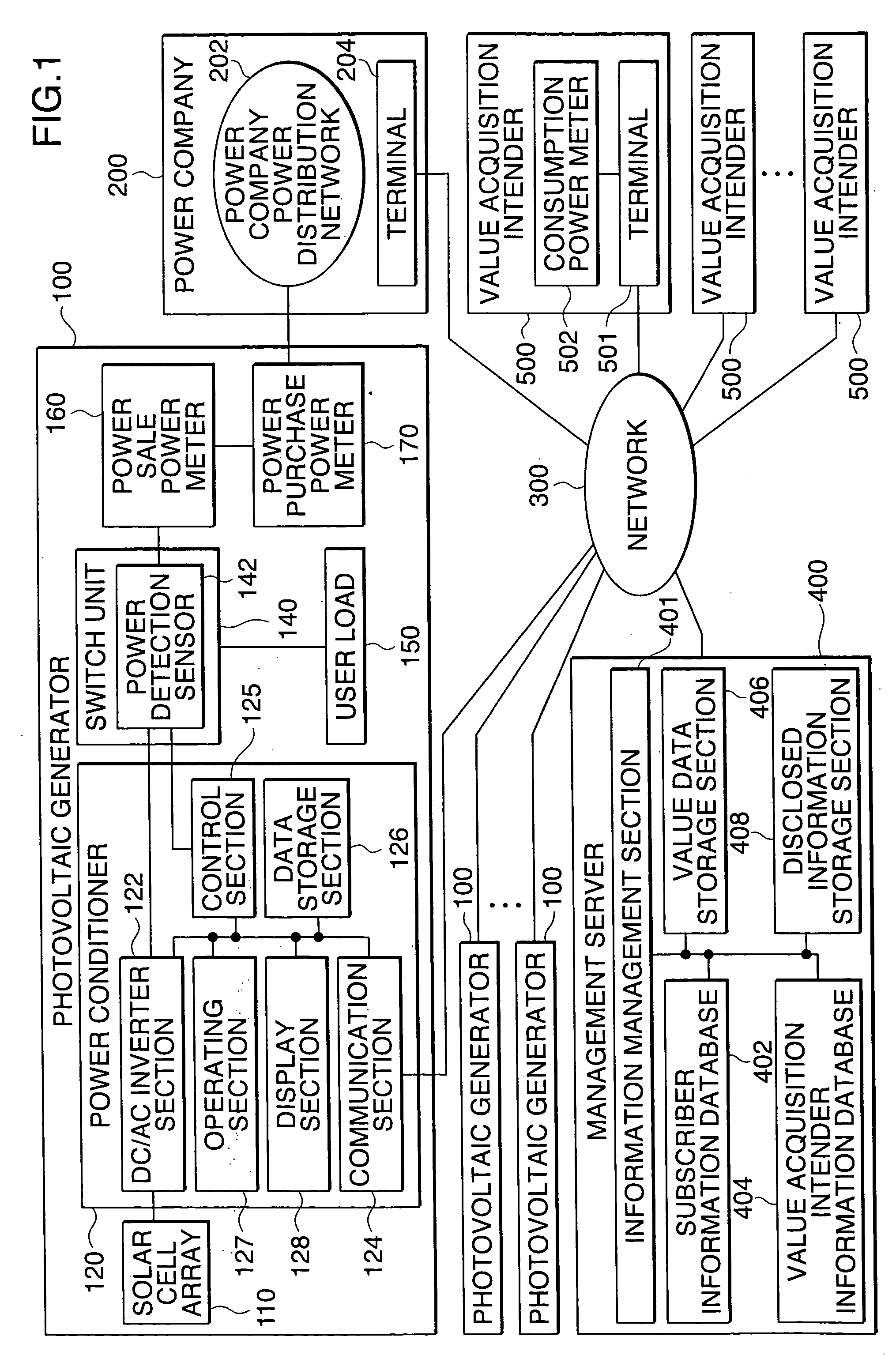
The invention relates to a generation facility management system using natural energy, and an object of the invention is to promote introduction of a generation facility by giving a consideration for generated and consumed power.The generation facility management system is characterized in including a generation facility using natural energy and a management server for managing power information on the generation facility, wherein the generation facility includes: an energy obtaining section for obtaining natural energy; a power generating section for generating power from the obtained natural energy; an information control section for creating generated power information on the power generated by the power generating section; and a communication section for transmitting the power information to the management server, and the management server includes an information management section for determining a consideration for the power information transmitted from the generation facility by using predetermined consideration information.

Description

TECHNICAL FIELD[0001]The present invention relates to a generation facility management system for managing power generated by a generation facility with small environmental load, and particularly relates to the generation facility management system for managing power generated by natural energy. Further specifically, the present invention relates to the generation facility management system having a function capable of setting a value of the power generated by the generation facility with small environmental load and further the value of the power generated by natural energy.BACKGROUND ART[0002]From a growing consciousness on the environment in recent years, introduction of a generation facility using with small environmental load, particularly the generation facility using natural energy is promoted on a global basis. At present, introduction of these facilities has been promoted by overly or partially subsidized by support measures by subsidy of each country.[0003]In order to expe...

Claims


Application Information

Patent Timeline
IPC IPC(8): G05D11/00H02J4/00F24J3/06G06F17/00G06F19/00F24V50/00G06Q50/00G06Q50/06H02J1/00H02J3/00H02J3/06H02J3/38
CPCG06Q50/06H02J3/06Y04S10/60Y04S10/54H02J3/386Y02E10/563Y02E10/763H02J3/383H02J2300/28H02J2300/24H02J3/381H02J3/004Y02E10/56Y02E10/76Y04S10/50
Inventor YAMADA, KAZUOFUKE, NOBUHIROFUKUSHIMA, TAKASHIKISHIMOTO, KATSUSHI
Owner SHARP KK
Learn More