Wiper blade structure

a technology of a wedge blade and a structure, applied in the field of wedge blades, can solve the problems of unchosen accessories left behind and thus wasted, unfavorable customer service, and high manufacturing cost, and achieve the effects of reducing manufacturing cost, facilitating close contact, and reducing manufacturing cos

Inactive Publication Date: 2008-10-02
CHENG MING HUI
View PDF10 Cites 53 Cited by
  • Summary
  • Abstract
  • Description
  • Claims
  • Application Information

AI Technical Summary

Benefits of technology

[0005]The wiper blade structure of the present invention is provided for remedying the aforementioned drawbacks of the conventional wiper blade structures. The disclosed wiper blade structure provides a novel structure that allows for easy assembly. Also, the disclosed structure is compatible with various types of vehicle wiper arms and facilitates close contact between the wiper blade and the windshield glass, while also allows the manufacturing cost thereof to be reduced.
[0006]It is one objective of the present invention to provide a wiper blade structure, which has pin holes and clamping recess provided on the opposite ends, and upper as well as lower edges of the laterals of the connecting adapter and the protective lid of the pivot assembly so as to engage various types of vehicle wiper arms. Thereby the need for additional accessories of the wiper blade assembly can be eliminated, and consequently, the purposes of convenient use and reduced manufacturing cost can be achieved.
[0007]It is another objective of the present invention to provide a wiper blade structure, which has rivets provided at the central portion of the pivot socket and positioning pieces arranged at th

Problems solved by technology

However, with the increment of the components of the wiper blade, the manufacturing cost can be immediately raised.
Meantime, during actual use, since the consumer can merely choose one of the accessories to use, the unchosen accessories are left aside and thus wasted.
For such a structure, high precision is required of the processing process; otherwise, the joints between the pivot socket and the resilient strip may be liable to loosening, and the efficiency of windshield wiping can be consequently depressed.
Though the disclosure remedy helps to overcome the disadvantage of loosening joints of the previously recited US Patent, the restriction caused by the coupled clips and

Method used


Image

  • Wiper blade structure
  • Wiper blade structure
  • Wiper blade structure

Examples


Embodiment Construction

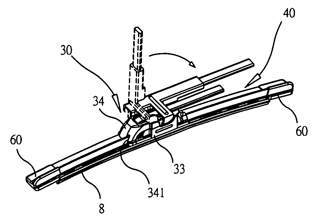
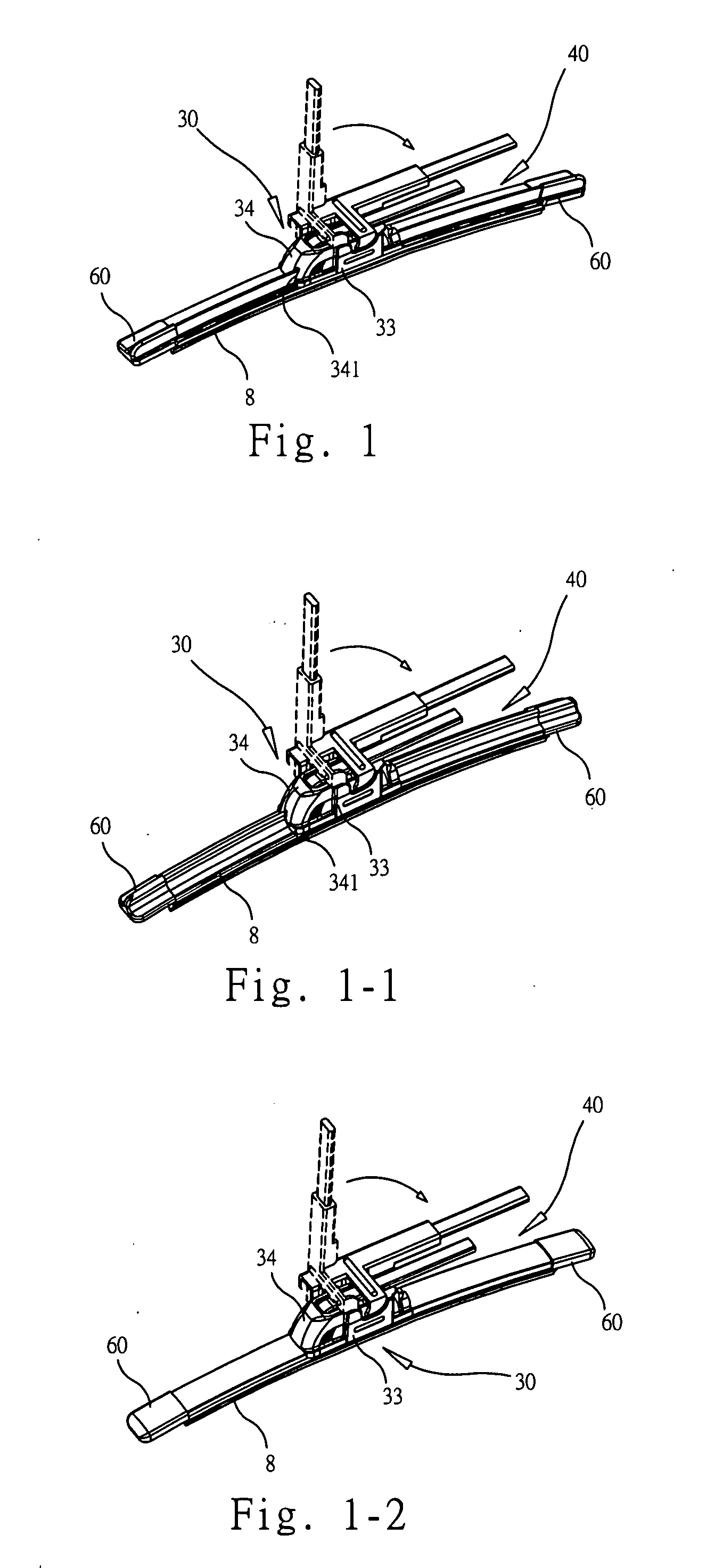
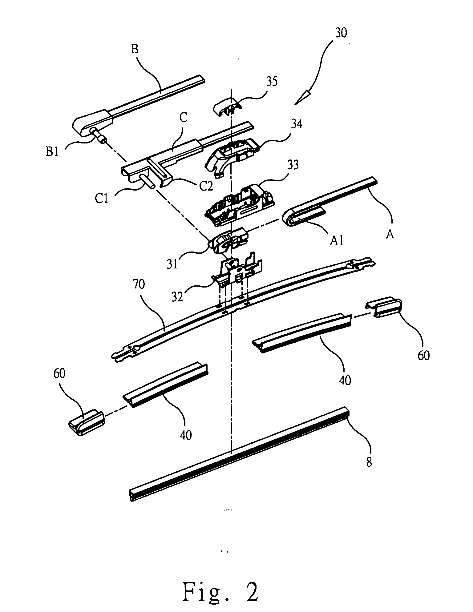
[0024]Please refer to FIG. 1 for the assembly drawing of one preferred embodiment of the present invention. The disclosed wiper blade structure comprises a pivot assembly 30, a plurality of deflectors 40, a plurality of end ferrule caps 60, a resilient strip 70 (as shown in FIG. 2), and a blade element 8. The pivot assembly 30 further comprises a connecting adapter 31 and a pivot socket 32. As can be seen in FIG. 2, a protective casing 33 and a protective lid 34 are provided around the periphery of the connecting adapter 31 and the pivot socket 32 for the purpose of protection. Thereupon, by connecting the connecting adapter 31, the protective casing 33 and the protective lid 34 with a vehicle wiper arm, and then connecting the said assembly with the resilient strip 70 and the blade element 8 by means of the pivot socket 32, the wiper blade can be assembled with the vehicle wiper arm. Each of the deflectors 40 is composed of a rigid rubber strip 41 and a flexible deflecting plate 42...


PUM


Abstract

A wiper blade structure comprises a pivot assembly, a plurality of deflectors, a plurality of end ferrule caps, a resilient strip, and a blade element. The pivot assembly may comprise a connecting adapter for engaging various wiper arms and the connecting adapter is further coupled with a pivot socket settled on the resilient strip, so that the connecting adapter can be easily connected with various wiper arms. Besides, by the combining structure among the pivot socket, end ferrule caps and the resilient strip, as well as the combination among the deflectors, resilient strip and the blade element, the wiper blade can firmly and closely contact the windshield glass, so that the defects of the conventional wiper blade structures can be remedied. Thus, the disclosed subject matter can perform improved efficiency of use and therefore is an invention having utilitarian value.

Description

BACKGROUND OF THE INVENTION[0001]1. Technical Field[0002]The present invention relates to a wiper blade and, more particularly, to an assembled structure of a wiper blade that is compatible with various wiper arms of a vehicle and facilitates tight, and firm contact between the wiper blade and the windshield glass so as to remedy the drawbacks of the conventional wiper blade structure.[0003]2. Description of Related Art[0004]Presently, many different types of wiper blade structures have been provided for addressing some particular problems. For instance, Taiwan Patent M269236 (Application Number 93212160) discloses a wiper blade structure that is compatible with a variety of wiper arms of vehicles. More particularly, the wiper blade structure of M269236 implements a connector and some accessories for being collocated with the connector to satisfy the different demands of different structures of wiper arms. However, with the increment of the components of the wiper blade, the manufac...

Claims


Application Information

Patent Timeline
IPC IPC(8): B60S1/38
CPCB60S1/381B60S1/3856B60S1/3867B60S1/3879B60S1/3881B60S1/3887B60S1/3894B60S1/40B60S1/4003B60S1/4009B60S1/407B60S2001/3822
Inventor CHENG, MING-HUI
Owner CHENG MING HUI
Why Eureka
Try Eureka