Motor assembly for steam vacuum cleaner

a technology of motor assembly and vacuum cleaner, which is applied in the direction of carpet cleaners, liquid fuel engines, bowling games, etc., can solve the problems of less user-friendly type of vacuum, large contact area with the floor, and difficulty in maneuvering the vacuum in order to clean under and/or around certain objects such as beds or couches, etc., to maximize the cooling efficiency of wet type motor

Inactive Publication Date: 2008-10-02
HAAN
View PDF6 Cites 3 Cited by
  • Summary
  • Abstract
  • Description
  • Claims
  • Application Information

AI Technical Summary

Benefits of technology

[0009]To address deficiencies of the related art, it is, therefore, an object of the present invention to provide a motor assembly for a steam vacuum cleaner capable of maximizing cooling efficiency of a wet type motor by separating the cold air sucked into a motor drive unit from the hot air which is exhausted from the unit after having been used.

Problems solved by technology

Because of this, the main body of the vacuum cleaner very large (having an undesirable height and width), making it difficult to maneuver the vacuum in order to clean under and / or around certain objects such as a bed or couch.
Additionally, because the main body of this vacuum is so bulky and large, its contact area with the floor is larger than many conventional vacuums.
Accordingly, this type of vacuum is less user friendly, making it more difficult to clean with this type of vacuum.
As a user pushes and pulls the vacuum to and fro, this ventilation blows away the dust on the floor in various directions, making use of this prior art vacuum less efficient.
This filter becomes clogged up over time, and the filter must be removed and emptied and / or replaced.
The size, shape and location of the dust collection bin makes removal and replacement difficult.
Further, as the filter becomes clogged, the efficiency (suction) of the motor is decreased, thereby reducing the efficiency of the motor.
Still another adverse effect of the related art steam vacuum cleaner is that when in use for steam cleaning and / or vacuum cleaning, it is highly possible that the sucked-up steam enters the motor and causes an electrical short.
This type of motor has a low cooling efficiency.
The cool air sucked into the motor and the warm air exhausted from the motor are not separated, and the motor can, at times, overheat.

Method used


Image

  • Motor assembly for steam vacuum cleaner
  • Motor assembly for steam vacuum cleaner
  • Motor assembly for steam vacuum cleaner

Examples


Embodiment Construction

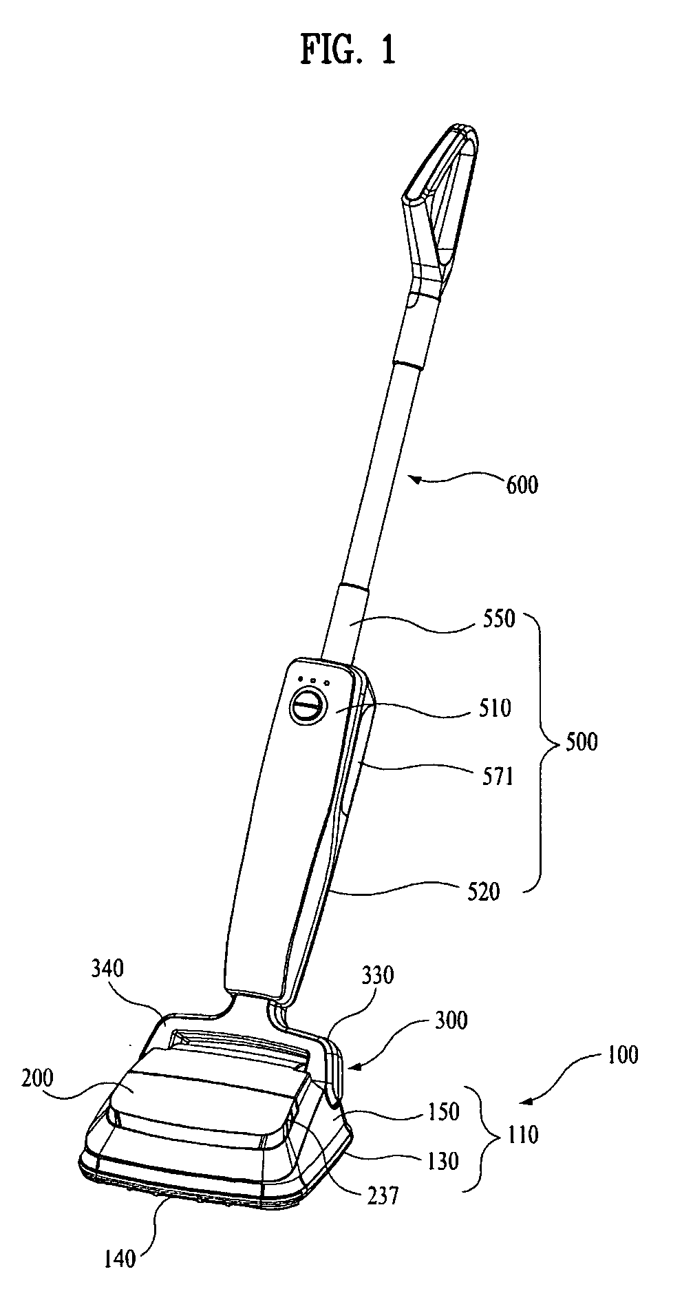
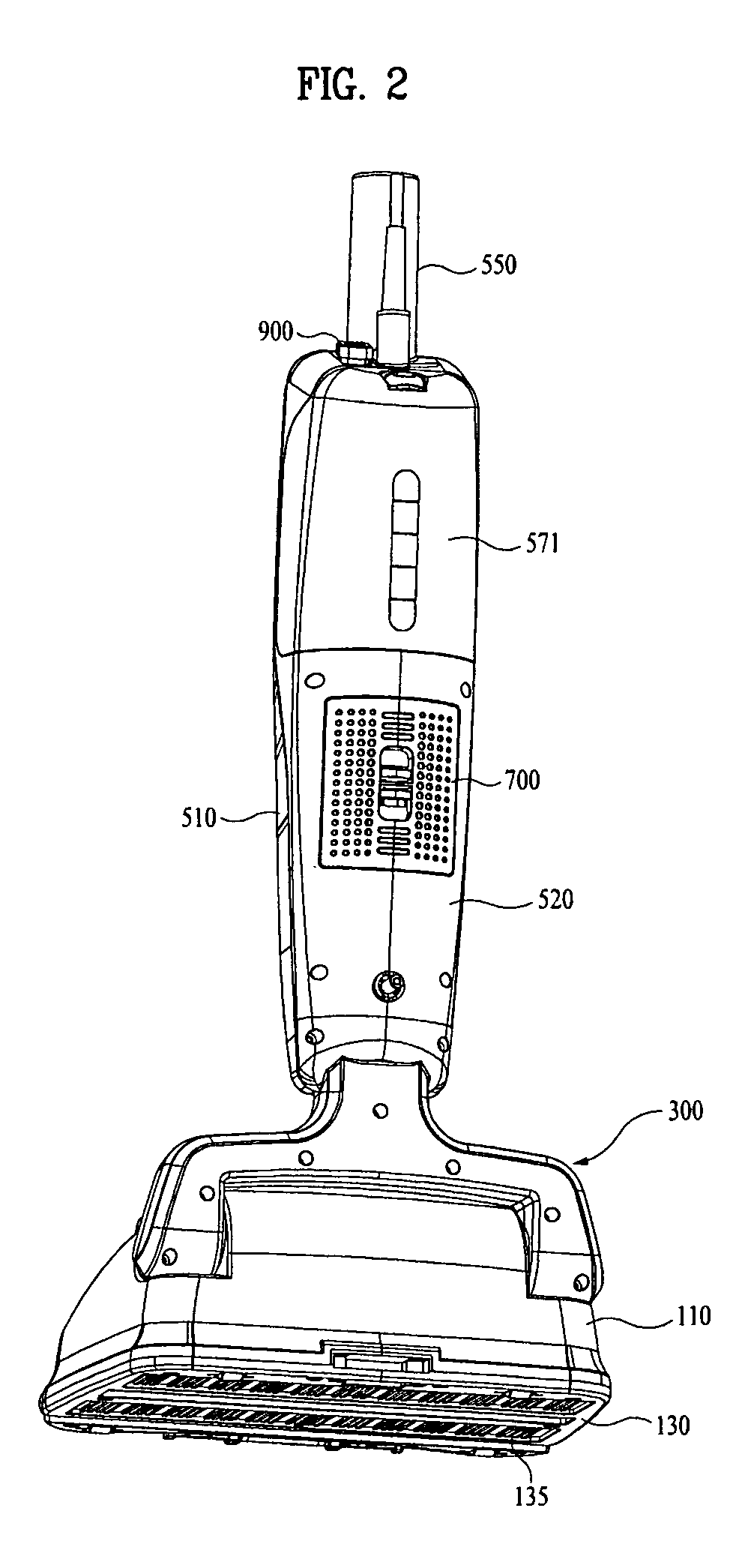
[0029]Hereinafter, preferred embodiments of the present invention will be set forth in detail with reference to the accompanying drawings so that those skilled in the art can easily carry out the invention. Referring to FIG. 1, there is shown a front perspective view of a steam vacuum cleaner according to a preferred embodiment of the present invention. FIG. 2 is a rear perspective view of the steam vacuum cleaner of FIG. 1. Referring to these figures (FIGS. 1 and 2), the steam vacuum cleaner is largely constituted by a base assembly 100, a main assembly 500, and a neck assembly 300 which is connected between the base assembly 100 and the main assembly 500.

[0030]The main assembly 500 has a pipe 550 extending therefrom and to which a length-adjustable mop handle 600 is connected in a detachable manner. The mop handle 600 is preferably comprised of a telescopic stick and a handle.

[0031]Referring still to FIG. 1 and FIG. 2, the base assembly 100 is comprised of a main body 110 which pr...


PUM


Abstract

A motor assembly for a steam vacuum cleaner comprises a flow separation packing which is coupled within a motor cooling casing between a cold air intake duct and an air exhaust duct, so as to maximize cooling efficiency of a wet type motor by separating the sucked cold air from the hot air having undergone a cooling operation.

Description

CROSS-REFERENCE(S) TO RELATED APPLICATIONS[0001]The present invention claims priority of Korean patent application number 10-2007-0032454, filed on Apr. 2, 2007, which is incorporated by reference in its entirety.BACKGROUND OF THE INVENTION[0002]The present invention relates to a motor assembly for a steam vacuum cleaner comprising a flow separation packing between a motor drive unit and a motor cooling casing, so as to maximize cooling efficiency of a wet type motor by separating the sucked cold air from the hot air having undergone a cooling operation.[0003]Korean utility model registration Nos. 20-0404402 and 20-0413652 and Korean patent application publication No. 10-2007-0027895 all disclose a steam vacuum cleaner where a dust collection bin, a suction motor, and a steam generator are all installed in the main body of the vacuum. Because of this, the main body of the vacuum cleaner very large (having an undesirable height and width), making it difficult to maneuver the vacuum i...

Claims


Application Information

Patent Timeline
Patent Type & Authority Applications(United States)
IPC IPC(8): A47L9/22A47L7/00
CPCA47L9/122A47L9/125A47L9/1409A47L9/22A47L11/34A47L11/40A47L11/4097F04D25/166F04D29/584F04D29/70H02K9/04F04D25/082F04D29/5806A47L9/10A47L11/20
Inventor HAAN, GYUNG-HEE
Owner HAAN
Why Eureka
Try Eureka