Power generation system

a power generation system and power generation technology, applied in the direction of machines/engines, vessel construction, marine propulsion, etc., can solve the problems of reducing the efficiency of steam turbines, and limiting the fluctuation ratio of turbine governing valve apertures b>38/b>, so as to prevent the reduction of steam turbine efficiency

Inactive Publication Date: 2008-10-02
THE TOKYO ELECTRIC POWER CO INC +1
View PDF4 Cites 7 Cited by
  • Summary
  • Abstract
  • Description
  • Claims
  • Application Information

AI Technical Summary

Benefits of technology

[0011]The present invention has been achieved to solve the above problems, and its object is to provide a power generation system that prevents a reduction in the efficiency of a steam turbine due to adjustment of the aperture of the turbine governing valve.

Problems solved by technology

As a result, there has been a problem in that the efficiency of the steam turbine 34 is reduced due to a loss in steam pressure at the turbine governing valve 38.
However, since the fluctuation ratio of the steam turbine 34 inlet temperature that can be handled by the steam turbine 34 is limited, also the fluctuation ratio of the aperture of the turbine governing valve 38 naturally becomes limited.
As a result, there has been a problem in that the steam turbine 34 cannot be operated so as to comply with the required electric power.

Method used


Image

  • Power generation system
  • Power generation system
  • Power generation system

Examples


Embodiment Construction

[0026]Hereunder, an embodiment of a power generation system according to the present invention is described, with reference to drawings.

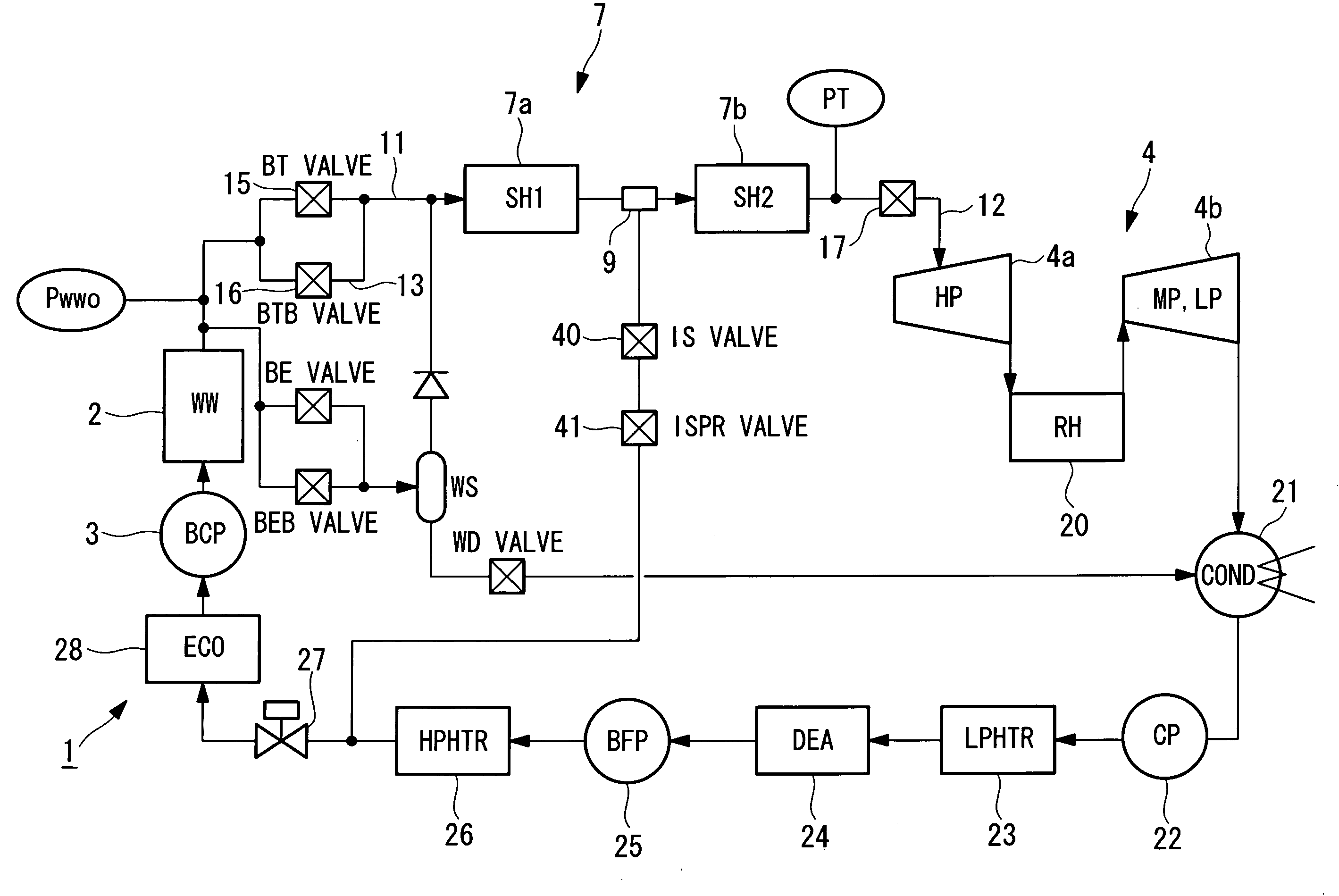
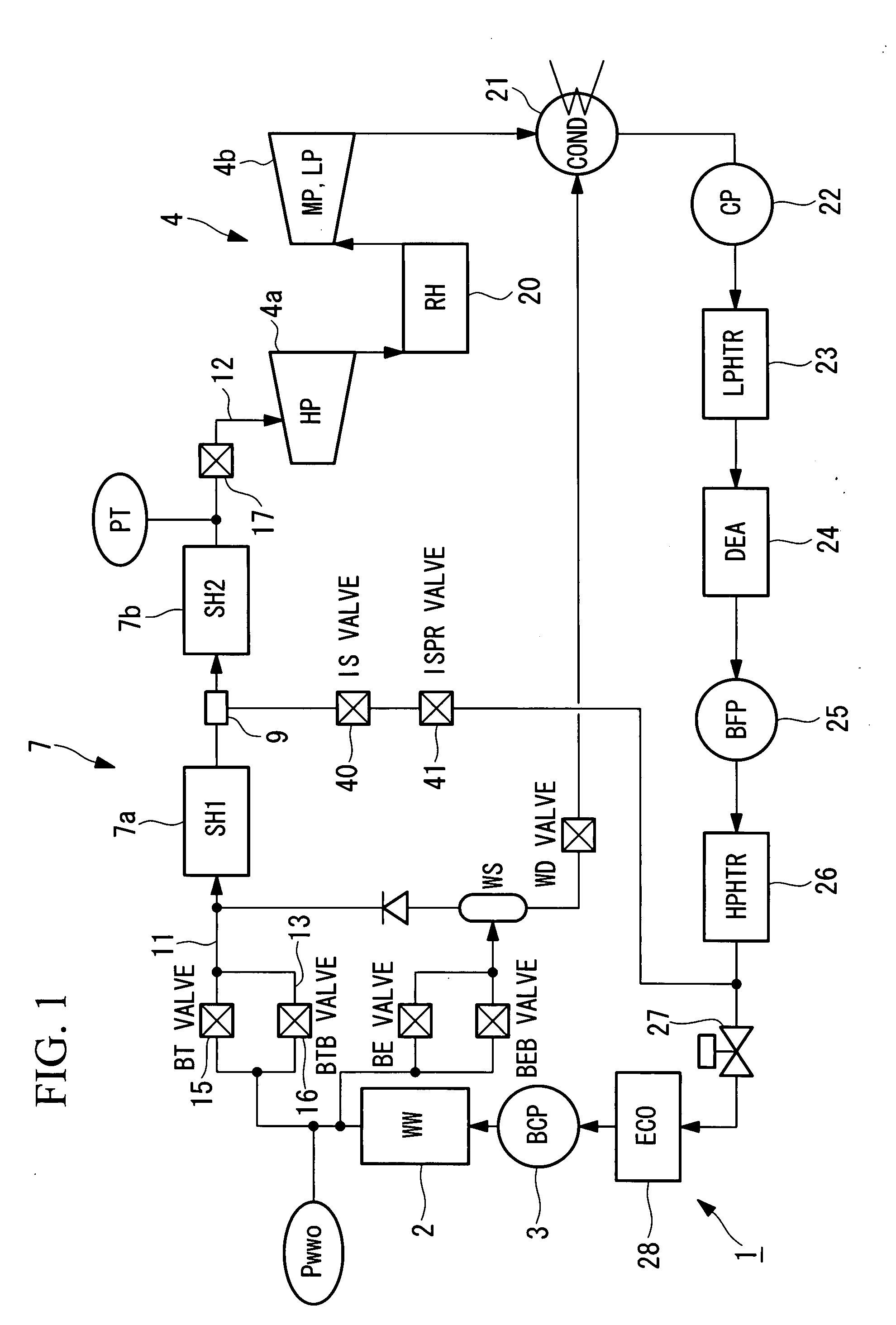
[0027]In FIG. 1, the main constituents of a power generation system 1 include: a furnace 2 for combusting a solid fuel or a liquid fuel; a boiler circulation pump 3 that causes water to flow through a water pipe (not shown in the drawing) provided within the furnace 2; a steam turbine 4 that generates electric power by rotating a turbine rotor using steam generated in the furnace 2; a superheater 7 that is provided between the furnace 2 and the steam turbine 4 and that superheats steam; a first steam piping 11 that connects the furnace 2 to the superheater 7; a second steam piping 12 that connects the superheater 7 to the steam turbine 4; a first valve 15 provided in the first steam piping 11; a turbine governing valve 17 provided in the second steam piping 12; a third steam piping 13 that is connected to the first steam piping 11 and bypasses the f...


PUM


Abstract

To provide a power generation system that prevents a reduction in the efficiency of a steam turbine due to an aperture adjustment of a turbine governing valve. There is provided a power generation system comprising: a furnace in which a solid fuel or a liquid fuel is combusted; a steam turbine that generates electric power by rotating a turbine rotor using steam generated by the furnace; a superheater that is provided between the furnace and the steam turbine and that superheats the steam; a first steam piping that connects the furnace to the superheater; a second steam piping that connects the superheater to the steam turbine; a first valve provided in the first steam piping; a turbine governing valve provided in the second steam piping; and a control section that adjusts an aperture of the first valve according to a load of the steam turbine.

Description

BACKGROUND OF THE INVENTION[0001]1. Field of the Invention[0002]The present invention relates to a power generation system having a constant pressure once-through boiler.[0003]This application is based on Japanese Patent Application No. 2007-091784, the content of which is incorporated herein by reference.[0004]2. Description of Related Art[0005]In thermal electric power plants, power generation systems that have a constant pressure once-through boiler and a steam turbine as the main constituents are often employed (See for example, Japanese Unexamined Patent Application, Publication No. Hei 9-96227). Such power generation systems generate electric power by means of a steam turbine using steam generated by a constant pressure once-through boiler.[0006]FIG. 3 shows an example of a conventional power generation system.[0007]First, the steam for driving a steam turbine 34 is generated by a furnace 32. The steam generated by the furnace 32 flows through a first steam piping 31 provided ...

Claims


Application Information

Patent Timeline
Patent Type & Authority Applications(United States)
IPC IPC(8): F01K13/02
CPCF01K7/24F01K13/02
Inventor ONAKA, IKUOKOUNO, YOSHIAKIMATSUOKA, TOSHIKIMURAKI, TAISHI
Owner THE TOKYO ELECTRIC POWER CO INC
Why Eureka
Try Eureka