Consumable electrode type gas shielded arc welding control apparatus and welding control method

a gas shielded arc welding and control apparatus technology, applied in the direction of welding/cutting media/materials, welding apparatus, manufacturing tools, etc., can solve the problems of small-sized spatters, blown off melt at the wire tip, and very unstable growth process, so as to reduce the generation of spatters in the middle/high current region and improve the quality of welding structures.

Inactive Publication Date: 2008-10-02
KOBE STEEL LTD
View PDF7 Cites 19 Cited by
  • Summary
  • Abstract
  • Description
  • Claims
  • Application Information

AI Technical Summary

Benefits of technology

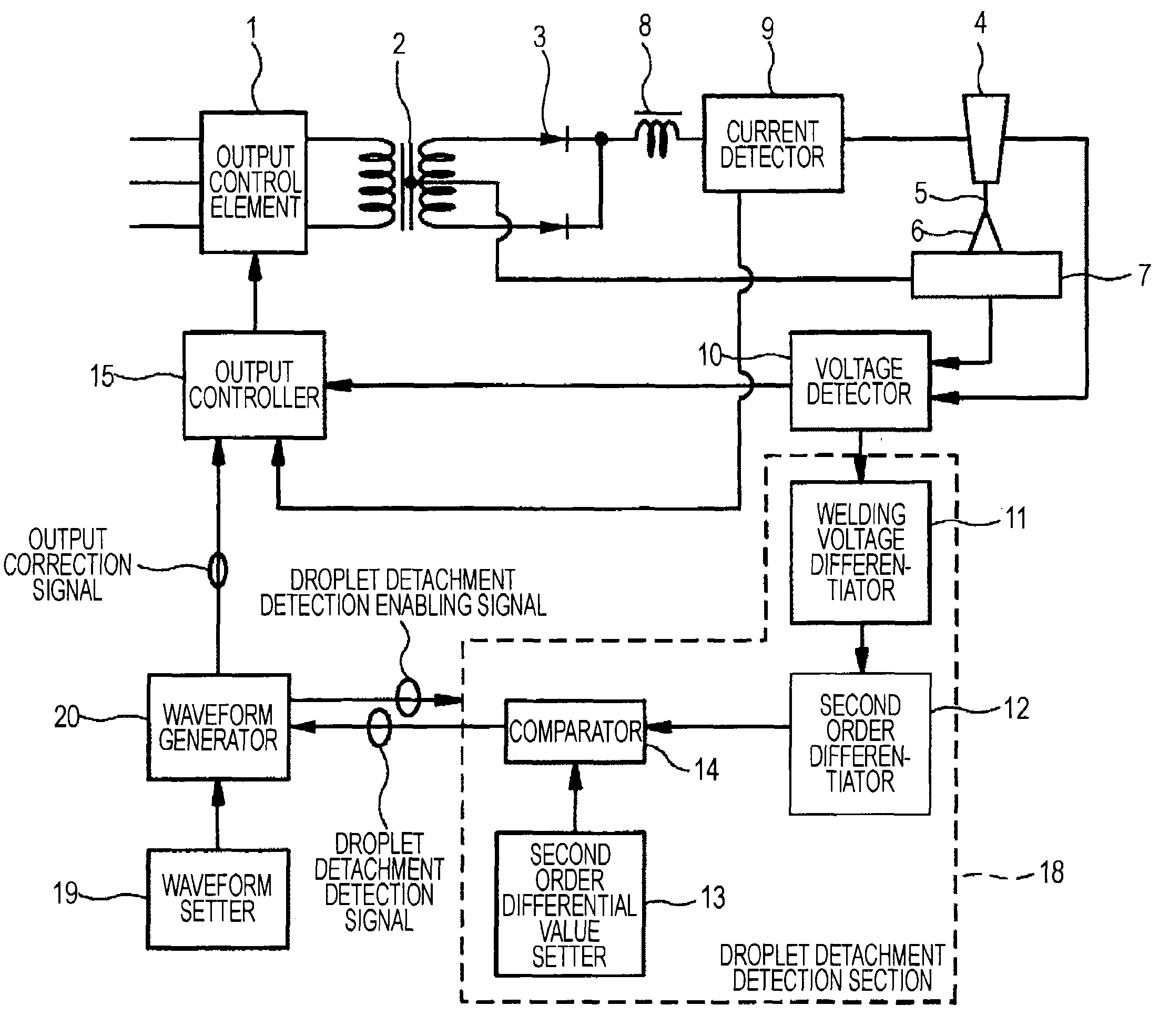
[0008]Accordingly, the present invention has been made in view of the above, and it is an object of the present invention to provide a welding control apparatus and welding control method capable of correctly detecting droplet detachment even if welding conditions are changed during the welding or wire extension lengths are changed (for example, in weaving welding). Further, depending on setting of a predetermined reference value for comparison, a timing just before the droplet detachment can be detected. Based on the droplet detachment detection, by switching the current to a current lower than that at the time of the detection, spatter generation in a middle / high current region can be reduced and quality of welding structures can be improved.
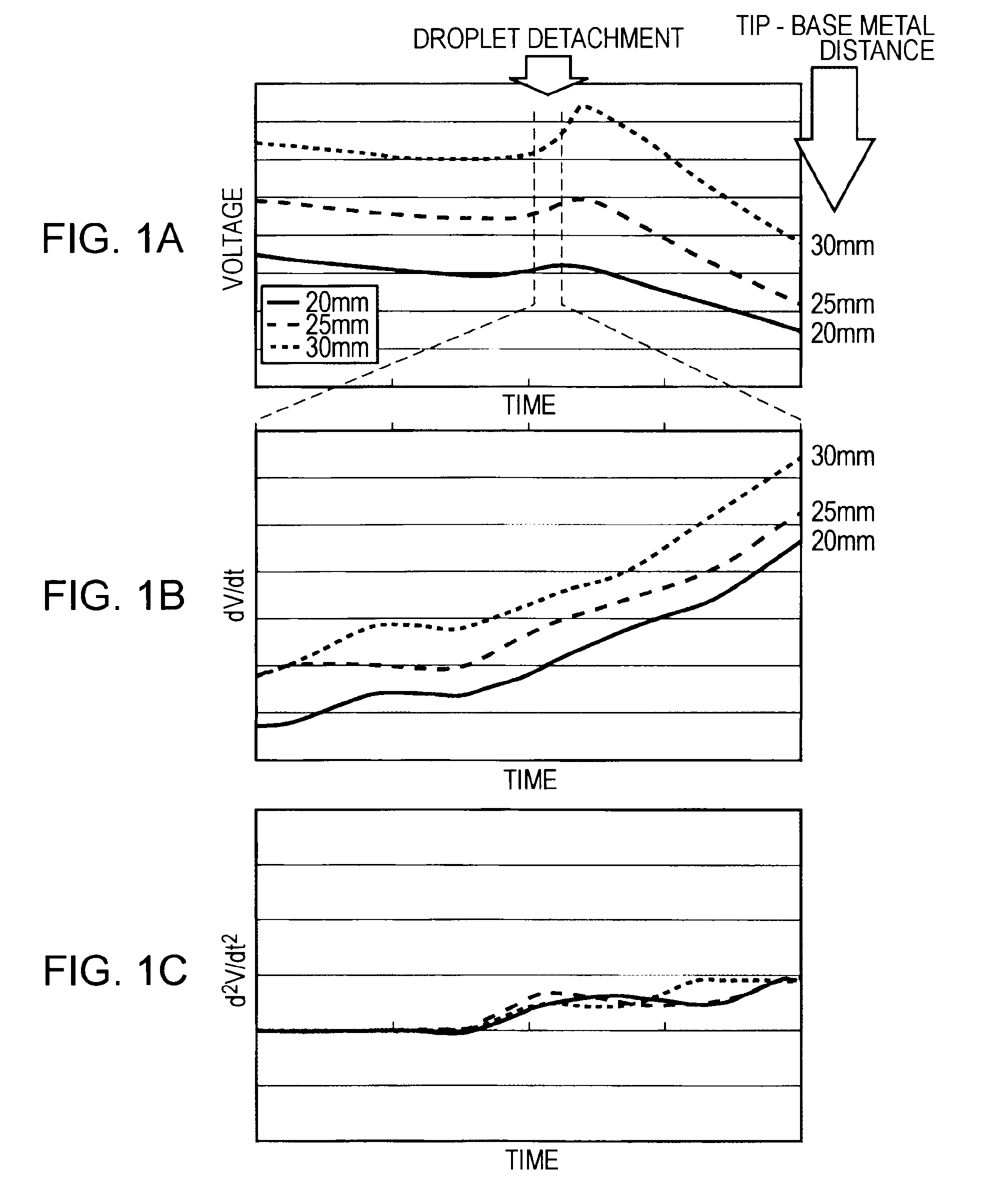
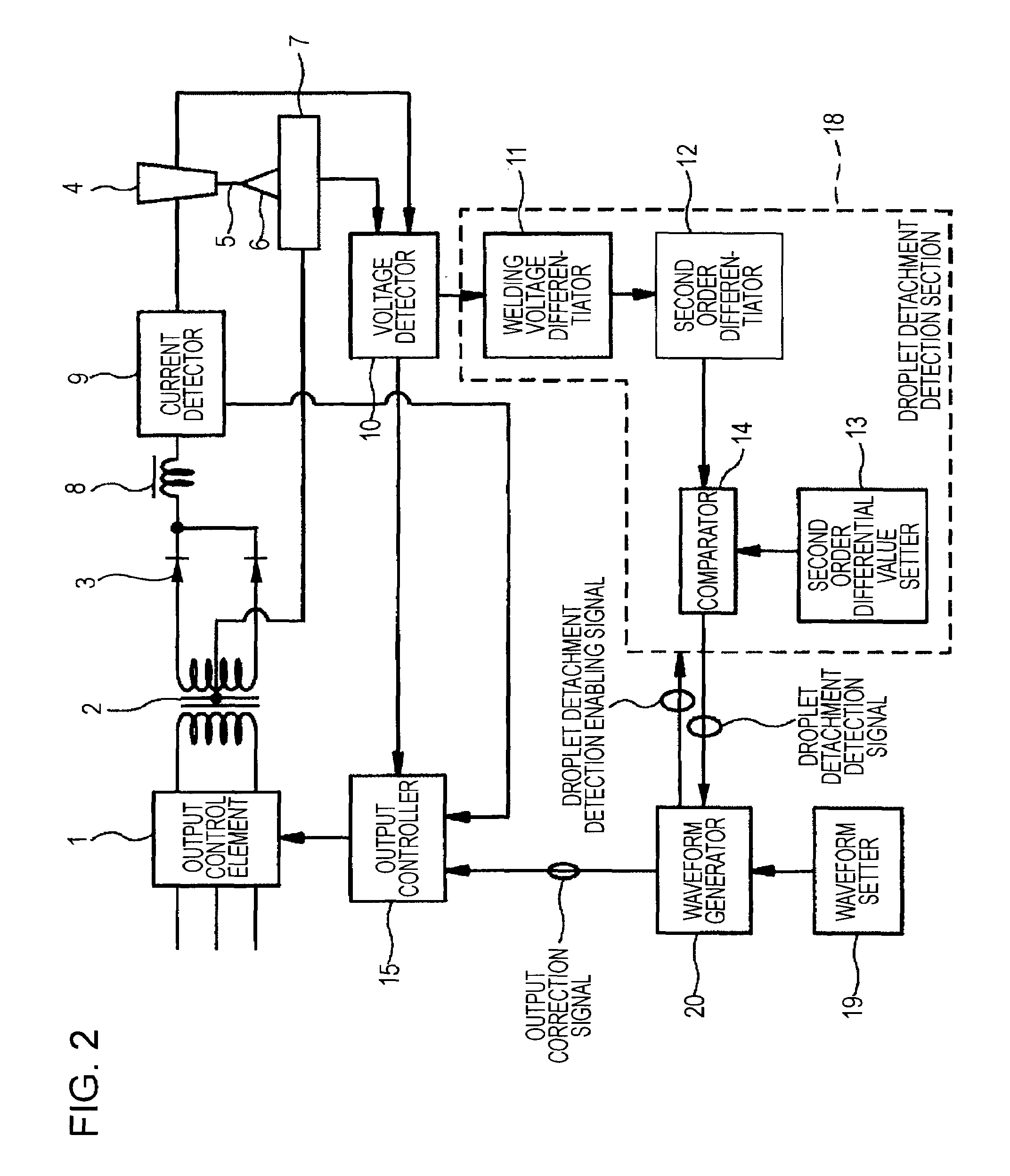
[0014]According to embodiments of the present invention, using a second order differential value of a welding voltage or an arc resistance, a detachment of a droplet or a timing just before the droplet detachment is detected. After the detection of the droplet detachment or the timing just before the droplet detachment, a current is immediately switched to a lower current than the current at the time of the droplet detachment. Accordingly, even if welding conditions are changed during the welding or wire extension lengths are changed (for example, in weaving welding), the droplet detachment can be correctly detected. Further, depending on setting of a predetermined reference value for comparison, it is possible to detect a timing just before the droplet detachment. After the droplet detachment detection, by switching the current to a predetermined current lower than that at the time of the detection, spatter generation in a middle / high current region can be largely reduced and quality of welding structures can be improved.

Problems solved by technology

However, the growth process is very unstable.
Moreover, after the detachment of the droplet, when the arc moves to the wire, the melt remaining at the wire tip is blown off, and small-sized spatters are formed.
The spatters deteriorate quality of welding structures.
However, in the control apparatus and method of the above known art, it is not possible to correctly detect the droplet detachment if welding conditions are changed during the welding and if wire extension lengths are changed (for example, weaving welding in a groove).
Such detection errors often occur in high current regions.
Accordingly, in the high current regions where spatter reduction is especially desired, the spatters are not reduced, and on the contrary, the detection errors increase the spatters.
As a result, the quality of the welding structures may be deteriorated.
Accordingly, it is not possible to solve the problem that the melt remaining at the wire tip is blown off and the small-sized spatters are generated.
Further, even if the method is used, the detection errors of the droplet detachment cannot be appropriately prevented.

Method used


Image

  • Consumable electrode type gas shielded arc welding control apparatus and welding control method
  • Consumable electrode type gas shielded arc welding control apparatus and welding control method
  • Consumable electrode type gas shielded arc welding control apparatus and welding control method

Examples


example 1

[0036]A gas shielded arc welding was performed using the welding control apparatuses according to the first and second embodiments shown in FIGS. 2 and 3, a solid wire of 1.2 mm in wire diameter for a consumable electrode wire, MAG (80% Ar+20% CO2) gas for a shielding gas. FIGS. 4A and 4B illustrate welding current waveforms, welding voltage waveforms, time second order differential values of the welding voltage d2V / dt2, time second order differential values of arc resistance d2R / dt2, and detachment detection signal waveforms at the time. Welding conditions were set as an average current of 240 A, an average voltage of 30 to 32 V, a welding speed of 30 cm per minute, and a wire extension length of 25 mm.

[0037]FIG. 4A illustrates that in response to a change in d2V / dt2 or d2R / dt2 , and immediately after a detachment detection signal was outputted, a welding current was switched to 120 A, and after 2.0 ms passed, the welding current returned to an original current (240 A). FIG. 4B ill...

example 2

[0038]A pulse arc welding was performed using the welding control apparatuses according to the first and second embodiments, a solid wire of 1.2 mm in wire diameter for a consumable electrode wire, CO2 for a shielding gas.

[0039]FIGS. 5A and 5B illustrate welding current waveforms, welding voltage waveforms, time second order differential values of the welding voltage d2V / dt2, and detachment detection signal waveforms in the welding. FIG. 6 illustrates the pulse waveform. As illustrated in FIG. 6, one droplet transfer per one cycle was realized by alternately outputting two pulse waveforms having different pulse peak currents Ip1 and Ip2, and pulse widths Tp1 and Tp2, detaching a droplet at a first pulse (Ip1, Tp1) in FIG. 5A, and forming a droplet at a second pulse (Ip2, Tp2) in FIGS. 5A and 5B. In a peak term or a trailing slope term of the first pulse, a droplet detachment enabling signal was outputted, and immediately after a droplet detachment or a timing just before the droplet...

example 3

[0040]A gas shielded arc welding using the welding control apparatuses shown in FIGS. 2 and 3, a solid wire of 1.2 mm in wire diameter for a consumable electrode wire, MAG (80% Ar+20% CO2) gas for a shielding gas, and a pulse arc welding using a 100% CO2 gas were performed. In flat position fillet welding, droplet detachment detection success rates in a known art (detection using time differential values dV / dt of voltage) and the present invention (detection using time second order differential values d2V / dt2 of voltage) were compared with each other. In the flat position fillet welding, the welding was performed under conditions of a weaving width of 6.0 mm, and a weaving frequency of 2 Hz, and wire extension lengths were momentarily changed. An average voltage was set to 300 A, voltage was set to appropriate voltage corresponding to each shielding gas, and a welding speed and a wire extension length were set to the same values as those of the first and second embodiments. Using a ...


PUM

PropertyMeasurementUnit
diameteraaaaaaaaaa
currentaaaaaaaaaa
currentaaaaaaaaaa

Abstract

In consumable electrode type gas shielded arc welding, a time second order differential value of a welding voltage or an arc resistance is calculated. Based on the second order differential value, a detachment of a droplet or a timing just before the detachment is detected. After the droplet detachment or the timing just before the detachment is detected, a welding current value is immediately switched to a predetermined current value lower than that at the time of the detection. According to the control, even if welding conditions are changed or wire extension lengths are changed in the welding, the droplet detachment can be correctly detected.

Description

BACKGROUND OF THE INVENTION[0001]1. Field of the Invention[0002]The present invention relates to a consumable electrode type gas shielded arc welding control apparatus for performing arc welding using consumable electrodes in a shielding gas atmosphere and a method for controlling the welding.[0003]2. Description of the Related Art[0004]In consumable electrode type gas shielded arc welding, as an electrode wire deteriorates, a droplet is formed at the wire tip. The droplet grows under influence of various forces such as gravity, arc reaction force, electromagnetic pinch force, and surface tension. Then, the droplet is detached and transferred to a molten pool. However, the growth process is very unstable. If the droplet is excessively pushed up and deformed, the droplet is detached under the influence of the arc resistance force without transferring to the molten pool in a wire extension direction, and diffuses as large-sized spatters. Accordingly, the droplet transfer cycle becomes...

Claims


Application Information

Patent Timeline
Patent Type & Authority Applications(United States)
IPC IPC(8): B23K9/173B23K9/09
CPCB23K9/092B23K9/173B23K9/095
Inventor YAMAZAKI, KEISATO, EIJINAKATSUKASA, SHOGOHONMA, MASAHIROSUZUKI, KEIICHI
Owner KOBE STEEL LTD
Why Eureka
Try Eureka