Metal injection molding process for bimetallic applications and airfoil

a bimetallic and metal injection molding technology, applied in the direction of turbines, blade accessories, wing shapes, etc., can solve the problems of difficult inspection, weakened heat affected zones, and high cost of methods

Inactive Publication Date: 2008-10-02
GENERAL ELECTRIC CO
View PDF15 Cites 41 Cited by
  • Summary
  • Abstract
  • Description
  • Claims
  • Application Information

AI Technical Summary

Problems solved by technology

These methods are expensive, can leave weakened heat affected zones and are often difficult to inspect.
Thermal and mechanical loads applied to components such as leading and trailing edges and tips of a gas turbine engine airfoil can adversely affect the airfoil's useful life.
Airfoils in gas turbine engines experience durability problems at the tip of the airfoil in the form of cracking due to thermally-induced stress and material loss due to oxidation and rubbing.
However, it is undesirable to upgrade the entire airfoil to a more thermal-resistant and oxidation resistant alloy because this increases component cost and perhaps weight.
However, their increased density and cost relative to conventional superalloys discourages their use for the manufacture of complete gas turbine components, so they are typically used as coatings or as small portions of components.
These highly environmentally resistant materials have proven difficult to attach to the basic airfoil alloys.

Method used


Image

  • Metal injection molding process for bimetallic applications and airfoil
  • Metal injection molding process for bimetallic applications and airfoil
  • Metal injection molding process for bimetallic applications and airfoil

Examples


Embodiment Construction

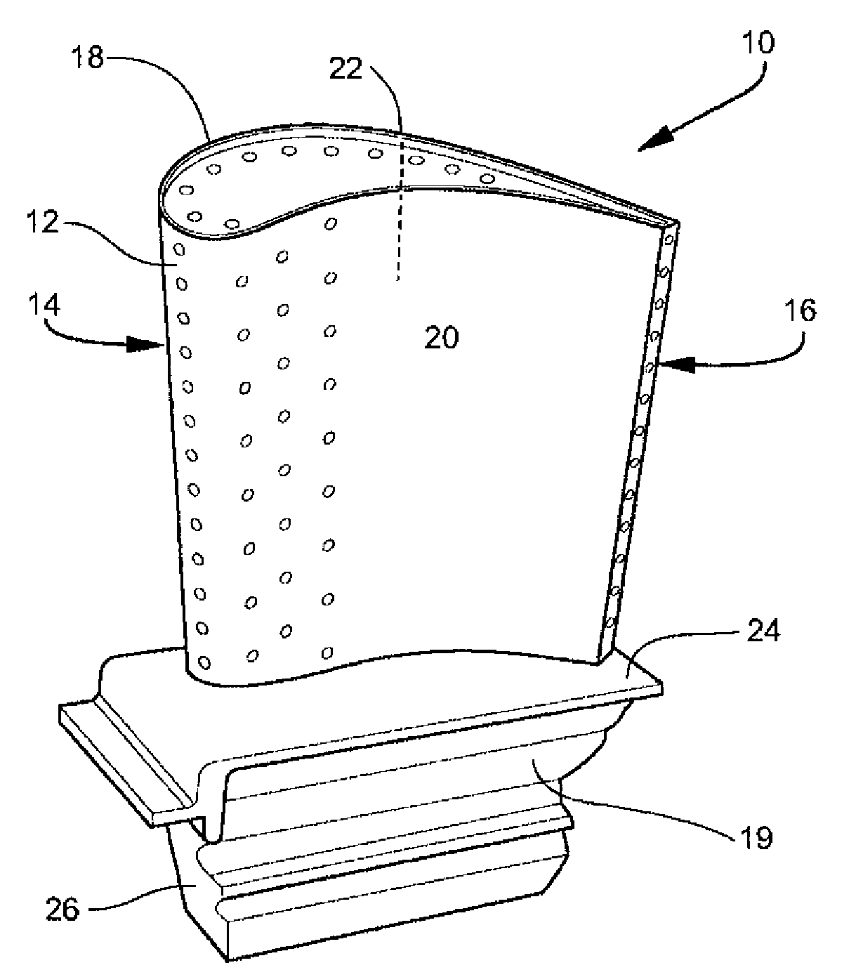
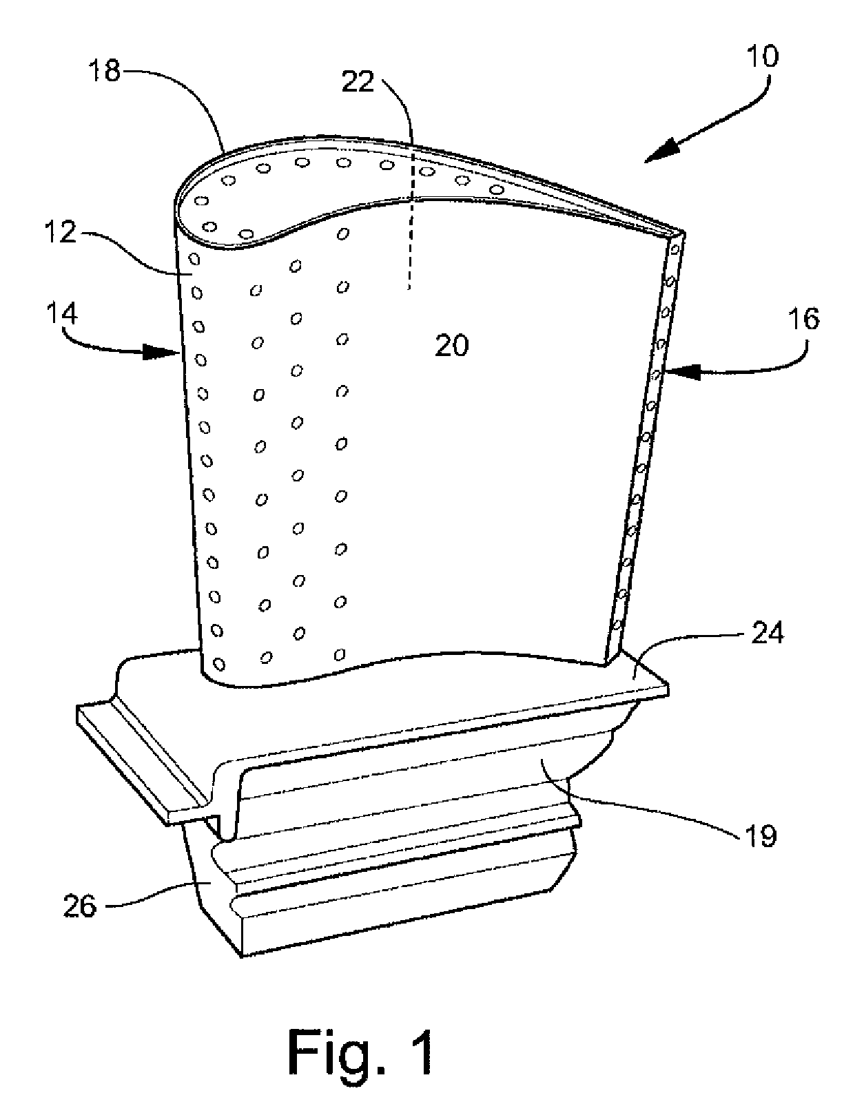
[0017]Referring to the drawings wherein identical reference numerals denote the same elements throughout the various views, FIGS. 1 and 2 depict an exemplary turbine blade 10 for a gas turbine engine. The present invention is equally applicable to the construction of other types of metallic components, such as stationary turbine vanes, frames, combustors, and the like. The turbine blade 10 includes an airfoil 12 having a leading edge 14, a trailing edge 16, a tip 18, a root 19, a concave pressure sidewall 20, a convex suction sidewall 22, a platform 24, and dovetail 26.

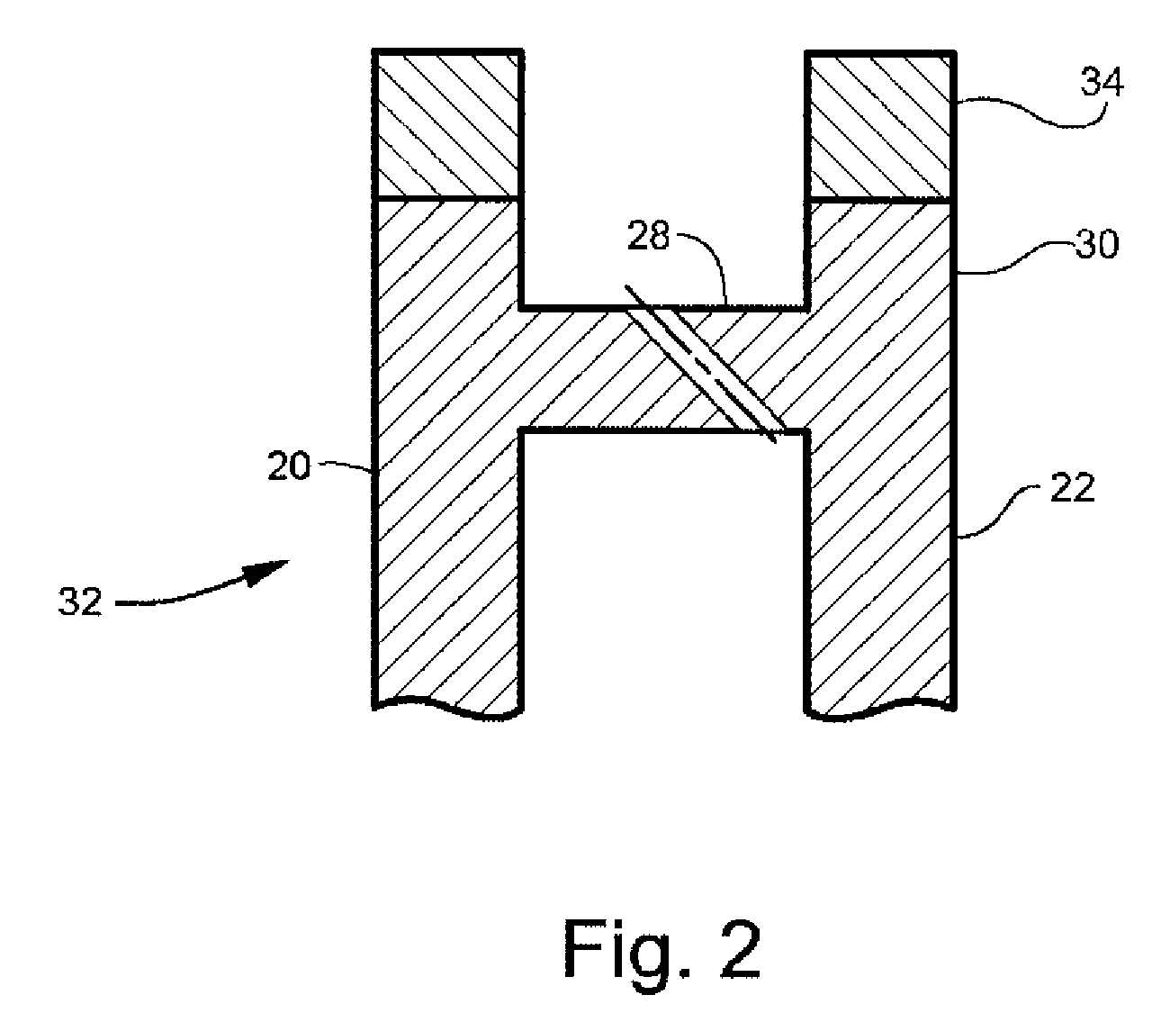
[0018]In accordance with the method of the present invention, the turbine blade 10 is constructed from first and second preforms 32 and 34. For example, the first preform 32 may include the pressure and suction sidewalls 22 and 24, a tip cap 28, and an integrally-formed partial height squealer tip 30. The first preform 32 typically comprises a known type of a nickel or cobalt-based superalloy having high-temperature s...


PUM

PropertyMeasurementUnit
temperatureaaaaaaaaaa
pressureaaaaaaaaaa
metallicaaaaaaaaaa

Abstract

A method of producing an airfoil including the steps of providing a first preform having a metallic powder of a first alloy, the first preform defining an airfoil body having curved pressure and suction sides. A tip cap is disposed between the pressure and suction sides of the airfoil at a radially outer end of the airfoil body. A partial height squealer tip extends radially outwards from the tip cap to provide a second preform that is a metallic powder of a second alloy different from the first alloy. The tip cap is formed in the shape of an extension of the squealer tip. The first and second preforms are sintered to consolidate the metal powders. An airfoil according to the method is also disclosed.

Description

BACKGROUND OF THE INVENTION[0001]This invention relates generally to high-temperature components for gas turbine engines and more particularly to components having a composition of more than one alloy.[0002]Current techniques for producing bimetallic components entails the use of joining processes such as tungsten inert gas welding, electron beam welding, inertia welding, brazing and similar processes. These methods are expensive, can leave weakened heat affected zones and are often difficult to inspect.[0003]Thermal and mechanical loads applied to components such as leading and trailing edges and tips of a gas turbine engine airfoil can adversely affect the airfoil's useful life. Airfoils in gas turbine engines experience durability problems at the tip of the airfoil in the form of cracking due to thermally-induced stress and material loss due to oxidation and rubbing. This can be addressed by using an alloy having increased resistance to environmental oxidation and corrosion. Howe...

Claims


Application Information

Patent Timeline
Patent Type & Authority Applications(United States)
IPC IPC(8): B64C3/14B22F7/00
CPCB22F3/225B22F5/04B22F7/062F01D5/20F01D5/28F05D2230/22B22F7/06F01D5/147
Inventor KELLY, THOMAS JOSEPHMEYER, MARK KEVINPARKS, MELISSA JANEFERRIGNO, STEPHEN JOSEPH
Owner GENERAL ELECTRIC CO
Why Eureka
Try Eureka