Imaging system

a technology of image processing and image, applied in the field of image processing system, can solve the problems of black spots, graininess in video, and a relatively long time for the current intensifier to recover from blooming, and the net loss of information during the recovery of the current intensifier and/or during the switch from the night vision camera to the visible camera could be very costly, so as to improve the operational life of the night vision camera, avoid visual information loss, and high efficiency

Inactive Publication Date: 2008-10-02
SUBRAHMANYAM PILLA
View PDF30 Cites 27 Cited by
  • Summary
  • Abstract
  • Description
  • Claims
  • Application Information

AI Technical Summary

Benefits of technology

[0007]Thus, in order to enhance the operational life of the night vision camera and to avoid loss of visual information, it is desirable to obtain a highly efficient night vision camera in which the occurrence of blooming is significantly reduced. It is also desirable to provide a system in which both the night vision and visible video displays are continuously on without the operator's intervention.
[0009]In another embodiment of the invention, there is provided a method for displaying an image of a scene, the method including splitting an incoming beam of radiation into a first and a second beam of radiation, the first beam of radiation including radiations substantially in a first spectral band and the second beam of radiation including radiations substantially in a second spectral band; intensifying the second beam of radiation, the intensifying including substantially absorbing in a photocathode all the radiations in the second beam of radiation and producing a flux of photoelectrons when the photocathode is exposed to the second beam of radiation; amplifying the flux of photoelectrons; and displaying an image of the scene in the second spectral band based on the amplified flux of electrons.

Problems solved by technology

Therefore, the regions that are exposed to high intensity light quickly lose their ability to provide high gain, leading to noise, black spots, and graininess in the video over continued operation of the camera.
It takes a relatively long time for the current intensifier to recover from the blooming.
The net loss of information during recovery of the current intensifier and / or during the switching from the night vision camera to the visible camera could be very costly under critical mission conditions.
Also, the repeated exposure to blooming causes the current intensifier to degrade quickly, as explained above, much faster than the manufacturer specified lifetime of the device leading to video noise.

Method used


Image

  • Imaging system
  • Imaging system
  • Imaging system

Examples


Embodiment Construction

[0023]The Figures described hereinafter illustrate various exemplary embodiments of the invention. These embodiments are in no way intended to be limiting, and are intended only as examples for facilitating an understanding of the principles of the present invention.

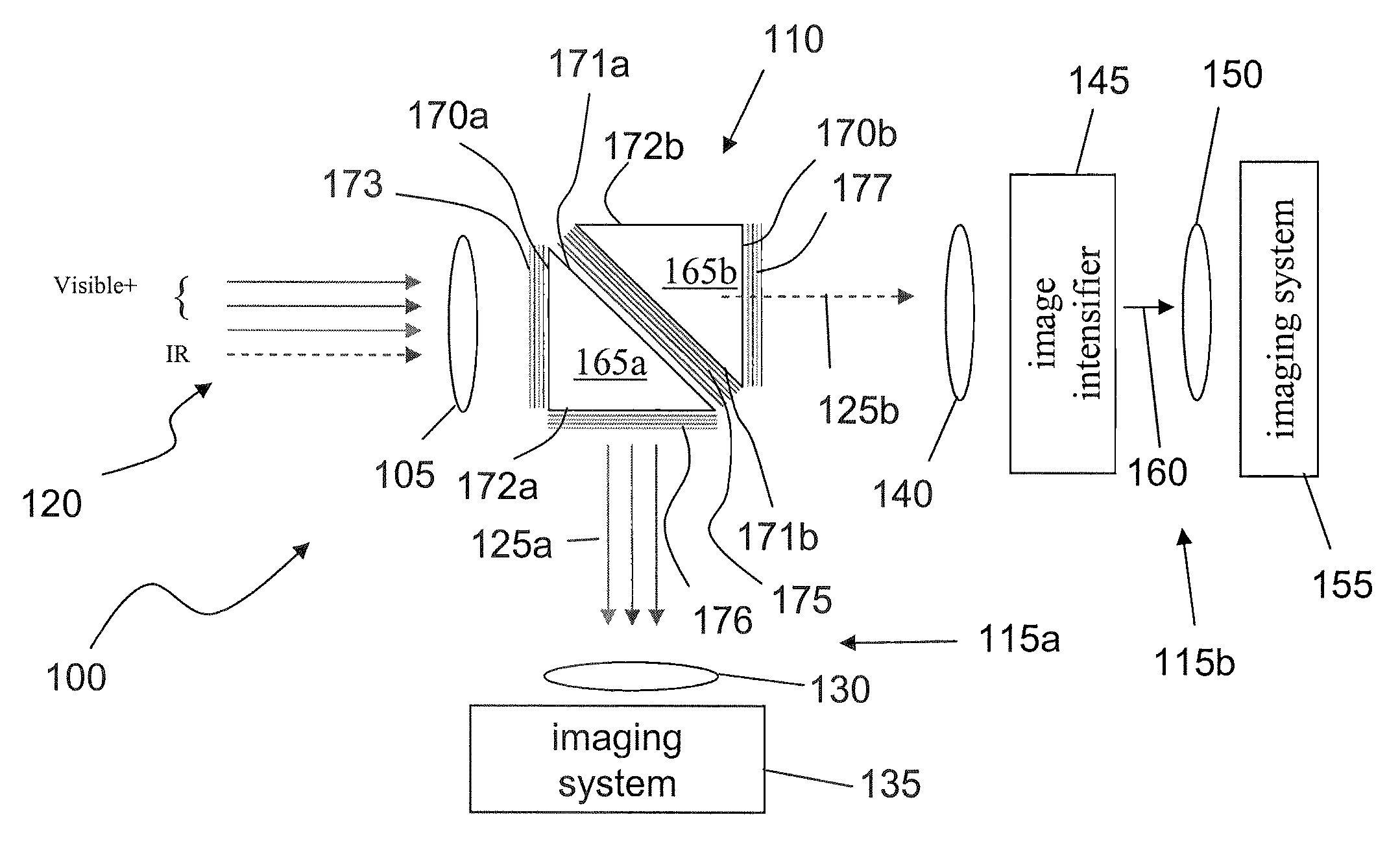
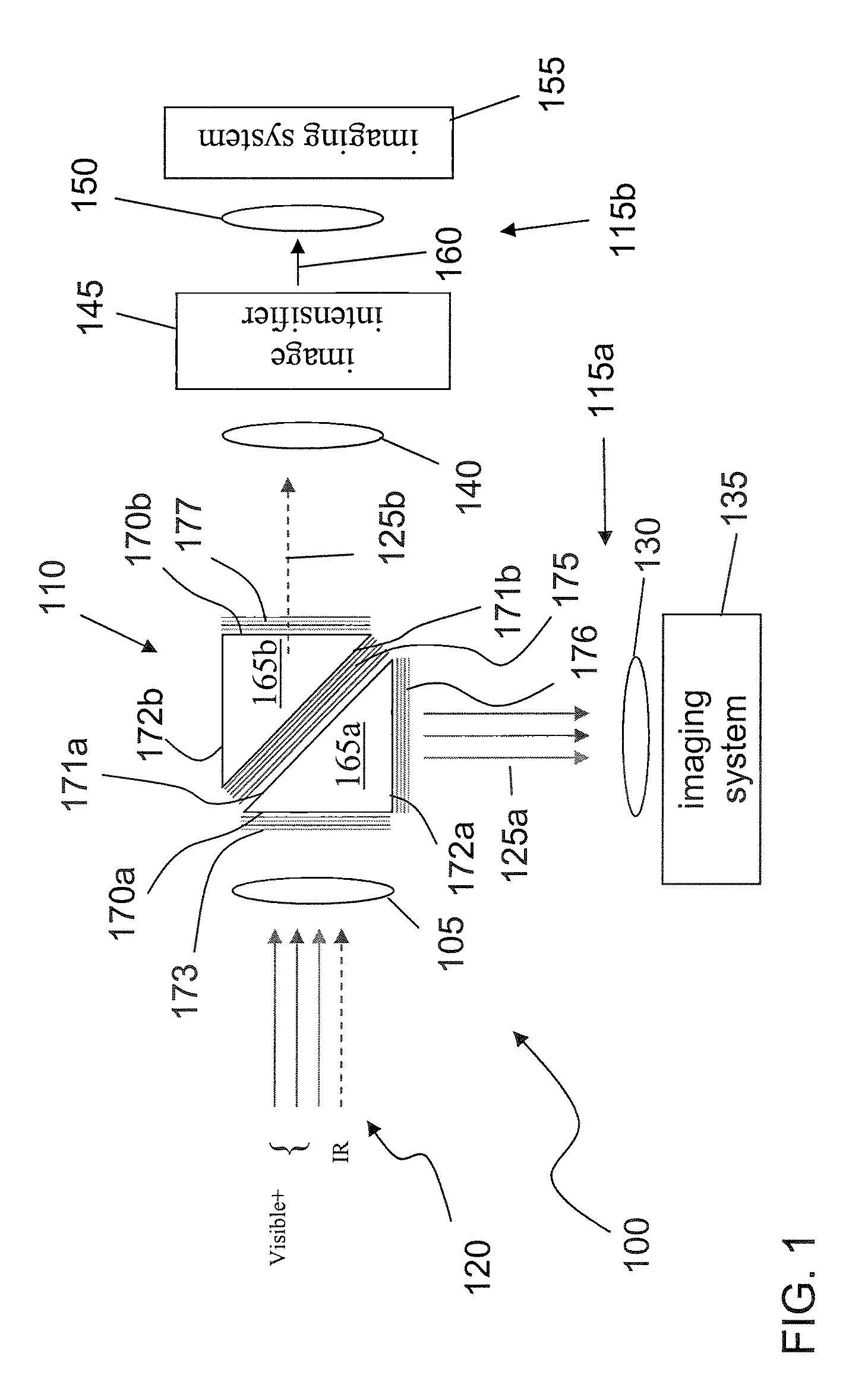
[0024]In an embodiment of the invention there is provided a visible—night vision combo optical system that is adapted to combine multiple spectral images of a scene. In one implementation, the system includes a spectral beam separator configured to split an incoming beam of radiation into a first and a second beam of radiation, the first beam of radiation including radiations substantially in a first spectral band and the second beam of radiation including radiations substantially in a second spectral band. The first spectral band may include the visible band. The second radiation band may include the near infra-red and portions of the deep infra-red. The optical system also includes an image intensifier configured to in...


PUM


Abstract

A viewing system configured to combine multiple spectral images of a scene, the system includes a spectral beam separator configured to split an incoming beam of radiation into a first and a second beam of radiation, the first beam of radiation including radiations substantially in a first spectral band and the second beam of radiation including radiations substantially in a second spectral band; an image intensifier configured to intensify the second beam of radiation, the image intensifier including a photocathode configured to produce a flux of photoelectrons with substantially increased efficiency when exposed to the second beam of radiation, the photocathode constructed and arranged to substantially absorb all the radiations in the second beam of radiation; a current amplifier configured to amplify the flux of photoelectrons; and a display system configured to display an image of the scene in the second spectral band based on the amplified flux of electrons simultaneously with an image of the scene in the first spectral band.

Description

BACKGROUND[0001]1. Field[0002]The present application relates to an imaging system.[0003]2. Description of Related Art[0004]Night vision cameras are the mainstay of security systems, search and rescue systems, air traffic control systems, as well as in certain astronomical and scientific missions. Night vision cameras are designed to operate in low illumination conditions where both low intensity visible light and near-IR light (both ambient as well as black body radiation) are utilized for image formation. In military and security related applications, due to the harsh and rapidly changing environmental conditions under which cameras need to operate, two separate video displays are provided, one for the visible spectrum and the other for the near infra-red spectrum. The color camera displays the image when the ambient light intensity is high enough, such as when the subject frame is illuminated by an external visible light source (at dawn or dusk). When the ambient light is low, th...

Claims


Application Information

Patent Timeline
Patent Type & Authority Applications(United States)
IPC IPC(8): H01L31/00G01T1/24
CPCH04N5/33H04N5/332H04N23/11
Inventor PILLA, SUBRAHMANYAMKADIYALA, SRINIVAS
Owner SUBRAHMANYAM PILLA
Why Eureka
Try Eureka