Solid-state microsecond capacitance charger for high voltage and pulsed power

a capacitance charger and microsecond technology, applied in pulse generators, pulse techniques, pulse manipulation, etc., can solve the problems of high price, large number of transistors summing through transformers, and relatively unreliable thyratrons

Inactive Publication Date: 2008-10-02
YAMPOLSKY JOSEPH
View PDF10 Cites 9 Cited by
  • Summary
  • Abstract
  • Description
  • Claims
  • Application Information

AI Technical Summary

Problems solved by technology

However, thyratrons are relatively unreliable and they have high complexity resulting in a high price.
Unfortunately, summing the output of a large number of transistors via a transformer is problematic because the transformer can cause dangerous overvoltage in the transistors.

Method used


Image

  • Solid-state microsecond capacitance charger for high voltage and pulsed power
  • Solid-state microsecond capacitance charger for high voltage and pulsed power
  • Solid-state microsecond capacitance charger for high voltage and pulsed power

Examples


Embodiment Construction

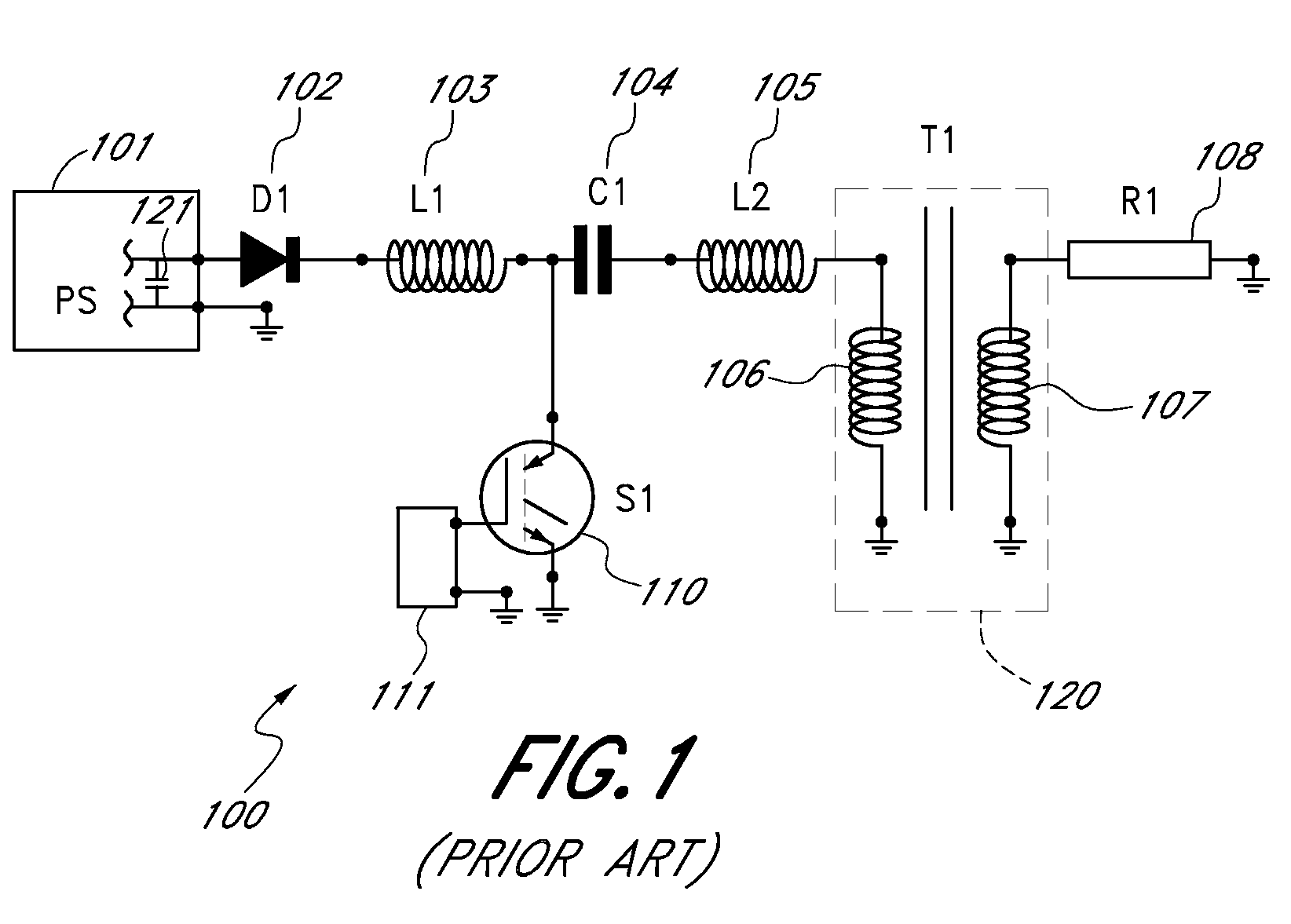
[0030]FIG. 1 shows a simple resonance charging system 100, where a power supply 101 provides a DC output voltage through a diode 102. The power supply 101 includes a filter capacitor 121 to filter the output voltage of the power supply 101. An output of the diode 102 is provided through an inductor 103 to a first terminal of an intermediate capacitor C1104. A second terminal of the capacitor C1104 is provided to ground through a series connection of an inductor 105 and a primary winding 106 of a transformer 120. A solid-state switch 110 is provided between the first terminal of the intermediate capacitor C1104 and ground. A control circuit 111 controls the solid-state switch 110. A secondary 107 of the transformer 120 is provided to a load 108. The charging system 100 doubles the voltage of the filter capacitor 121 by charging the intermediate capacitor.

[0031]In one embodiment, the capacitor C1104 is resonance charged to 320 volts from a 160 volt DC power supply. When the solid-stat...


PUM


Abstract

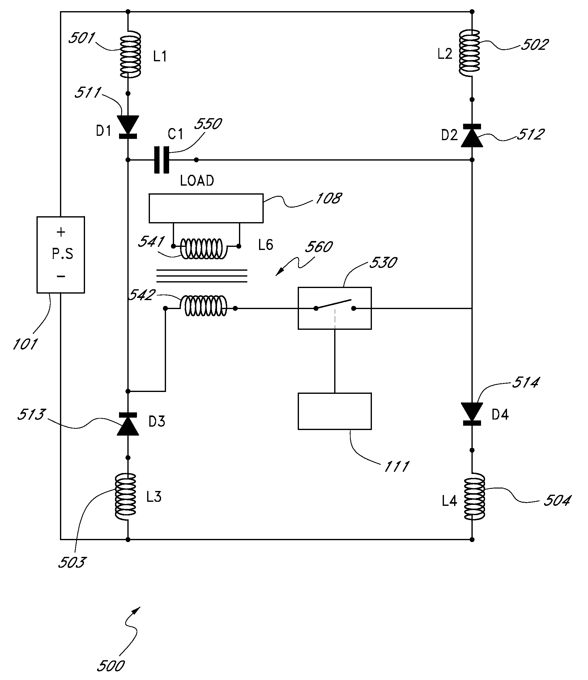
A solid-state high-voltage pulse generator based on a three-phase chopper capacitance charger is described. In a first phase, an intermediate capacitor is resonance-charged via a diode. In a second phase, the intermediate capacitor is discharged to the load through one or more solid-state switches. In a third phase, the energy remaining in the intermediate capacitor is returned to a power-supply filter capacitor. In one embodiment, the three-phase chopper includes an intermediate capacitor that is charged by first and fourth branches of a bridge and discharged by second and third branches of a bridge. In one embodiment, each branch of the bridge includes a diode in series with an inductor. In one embodiment, a composite solid-state switch connects the intermediate capacitor to a primary winding of an output transformer such that the intermediate capacitor discharges through the primary winding. In one embodiment, a secondary winding of the output transformer is provided to an output load. In one embodiment, the output load is a reactive load. In one embodiment, the output load is a capacitive load.

Description

CROSS-REFERENCE TO RELATED APPLICATIONS[0001]The present application is a continuation of application Ser. No. 10 / 351,644, filed Jan. 24, 2003, titled “SOLID-STATE MICROSECOND CAPACITANCE CHARGER FOR HIGH VOLTAGE AND PULSED POWER,” which claims priority benefit of U.S. Provisional Application No. 60 / 355,537, filed Feb. 6, 2002, titled “SOLID-STATE MICROSECOND CAPACITANCE CHARGER FOR HIGH VOLTAGE AND PULSED POWER,” the contents of which is hereby incorporated by reference in its entirety.BACKGROUND OF THE INVENTION[0002]1. Field of the Invention[0003]The invention relates to the field of solid-state high-voltage pulse power generators.[0004]2. Description of the Related Art[0005]High voltage pulse generators with fast rise time are typically used to drive gas discharge loads such as lasers, devices for pollution control applications and for plasma chemistry. In the past, such pulse generators used thyratrons to generate the desired pulses. However, thyratrons are relatively unreliabl...

Claims


Application Information

Patent Timeline
Patent Type & Authority Applications(United States)
IPC IPC(8): H03K3/021
CPCH01F3/14H01F19/04H01F27/40H01F30/06H01F38/00H01S3/097H01S3/09702H03K3/021H03K3/57H03K5/12
Inventor YAMPOLSKY, JOSEPH
Owner YAMPOLSKY JOSEPH
Why Eureka
Try Eureka