Drawing circuit of electro-optical display device, drawing method of electro-optical display device, electro-optical display device, and electronic apparatus

Inactive Publication Date: 2008-10-02
SEIKO EPSON CORP
View PDF15 Cites 8 Cited by
  • Summary
  • Abstract
  • Description
  • Claims
  • Application Information

AI Technical Summary

Benefits of technology

[0014]An advantage of some aspects of the invention is that it provides a drawing circuit of an electro-optical display device, a drawing method of the electro-optical dis

Problems solved by technology

Thus, it takes much time

Method used


Image

  • Drawing circuit of electro-optical display device, drawing method of electro-optical display device, electro-optical display device, and electronic apparatus
  • Drawing circuit of electro-optical display device, drawing method of electro-optical display device, electro-optical display device, and electronic apparatus
  • Drawing circuit of electro-optical display device, drawing method of electro-optical display device, electro-optical display device, and electronic apparatus

Examples


first embodiment

[0074]Hereinafter, an electrophoretic display device according to a first embodiment of the invention will be described with reference to FIGS. 1 to 14.

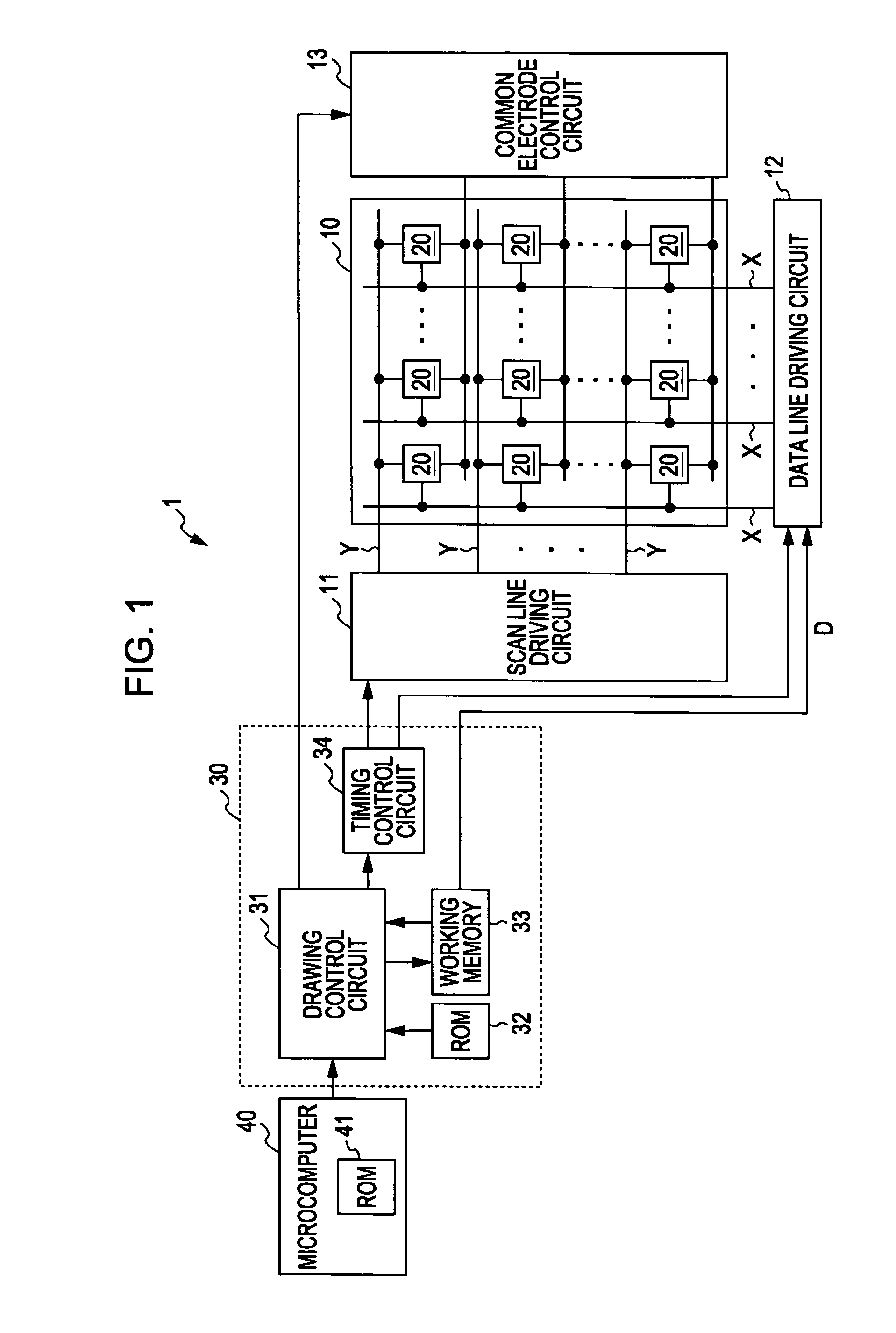
[0075]As shown in FIG. 1, an electrophoretic display device 1 includes an electrophoretic display panel 10 which is equal to that shown in FIG. 20, a driving circuit for driving the electrophoretic display panel 10, a drawing circuit 30 for controlling the driving circuit, and a microcomputer 40 for controlling the electrophoretic display device 1. In the present embodiment, the electrophoretic display device 1 which is used as a display unit of a wristwatch including a microcomputer having a low processing capability will be exemplarily described.

[0076]The electrophoretic display panel 10 includes pixel circuits 20 arranged in a matrix. That is, the pixel circuits 20 are arranged at intersections between a plurality of data lines X which extend in a column direction (a vertical direction of FIG. 1) and a plurality of scan lines Y wh...

second embodiment

[0125]Hereinafter, an electrophoretic display device according to a second embodiment of the invention will be described with reference to FIGS. 15 to 19. The electrophoretic display device according to the present embodiment is different from the first embodiment in a memory structure of the ROM 32 and the type of the control command stored in the microcomputer ROM 41. Hereinafter, the present embodiment will be described, concentrating on differences from the first embodiment. The electrophoretic display device according to the present embodiment includes the substantially same configuration as the electrophoretic display device 1 according to the first embodiment shown in FIG. 1.

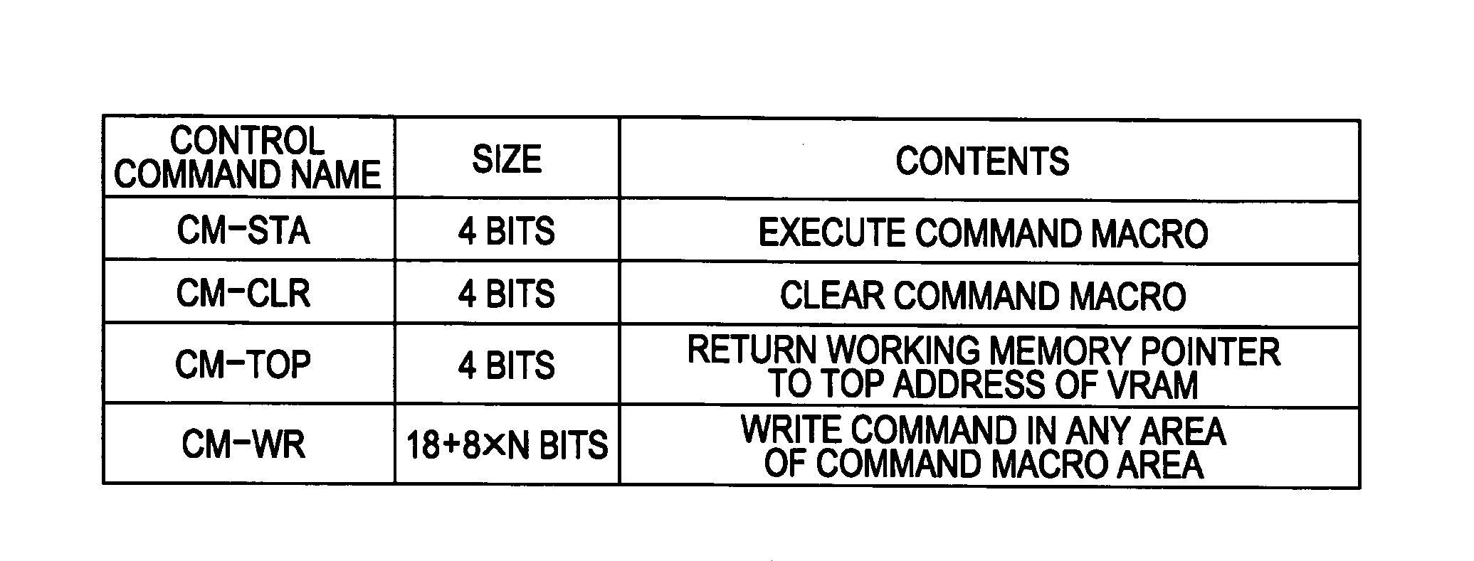
[0126]As shown in FIG. 15, the ROM 32 of the drawing circuit 30 includes a plurality of background blocks BG1 to BGn, a plurality of part blocks PT1 to PTm, and a command macro block CMB for storing the plurality of command macros (for example, command macros M1 and M2) composed of the plurality of comman...


PUM


Abstract

Provided is a drawing device of an electro-optical display device which includes a drawing circuit for outputting image data to a driving circuit for driving electro-optical elements of a display unit for displaying an image based on the image data, and a control circuit for controlling the drawing circuit, wherein the drawing circuit includes a first memory in which a plurality of image material data is previously stored, a first working memory having a working area in which the image data composed of at least one image material data is generated, a second working memory having a command information area in which a command signal for instructing execution of a predetermined process is written, and a drawing control circuit which writes the command signal in the command information area and generates command information composed of a plurality of command signals in the command information area, and the control circuit outputs a first control command signal for executing the command information to the drawing control circuit.

Description

BACKGROUND[0001]1. Technical Field[0002]The present invention relates to a drawing circuit of an electro-optical display device, a drawing method of the electro-optical display device, the electro-optical display device, and an electronic apparatus.[0003]2. Related Art[0004]As an electro-optical display device, an electrophoretic display device using an electrophoretic display phenomenon is known (for example, see JP-A-2002-116733). The electrophoretic display phenomenon indicates that, when an electric field is applied to a dispersion system in which particles (electrophoretic particles) are dispersed in liquid (dispersion medium), the particles migrate by Coulomb force.[0005]Such an electrophoretic display device includes an electrophoretic display panel, in which an electrode and another electrode face each other at a predetermined gap and division cells having a dispersion system sealed therein are interposed therebetween, and a peripheral circuit for applying an electric field ...

Claims


Application Information

Patent Timeline
IPC IPC(8): G09G3/34
CPCG09G3/04G09G3/344G09G2300/08
Inventor SAITO, HIDETOSHI
Owner SEIKO EPSON CORP
Why Eureka
Try Eureka