Deformable mirror apparatus

a mirror and mirror technology, applied in the direction of mirrors, mountings, instruments, etc., can solve the problems of lowering detection accuracy and resolution, and achieve the effect of small thermal expansion coefficien

Inactive Publication Date: 2008-10-02
KK TOSHIBA +1
View PDF4 Cites 3 Cited by
  • Summary
  • Abstract
  • Description
  • Claims
  • Application Information

AI Technical Summary

Benefits of technology

[0016]A deformable mirror apparatus according to a fifth aspect of the present invention includes: a substrate; a plurality of electrodes provided on the substrate; a spacer fixed on the substrate and surrounding the electrodes; a drive part comprising a membrane part disposed on the spacer so as to be opposed to the electrodes, a casing part having an opening at a bottom face of which the membrane part is expo

Problems solved by technology

Since an eyeball is not an ideal lens having no aberration, however, the eyeball has wave

Method used


Image

  • Deformable mirror apparatus
  • Deformable mirror apparatus
  • Deformable mirror apparatus

Examples


first embodiment

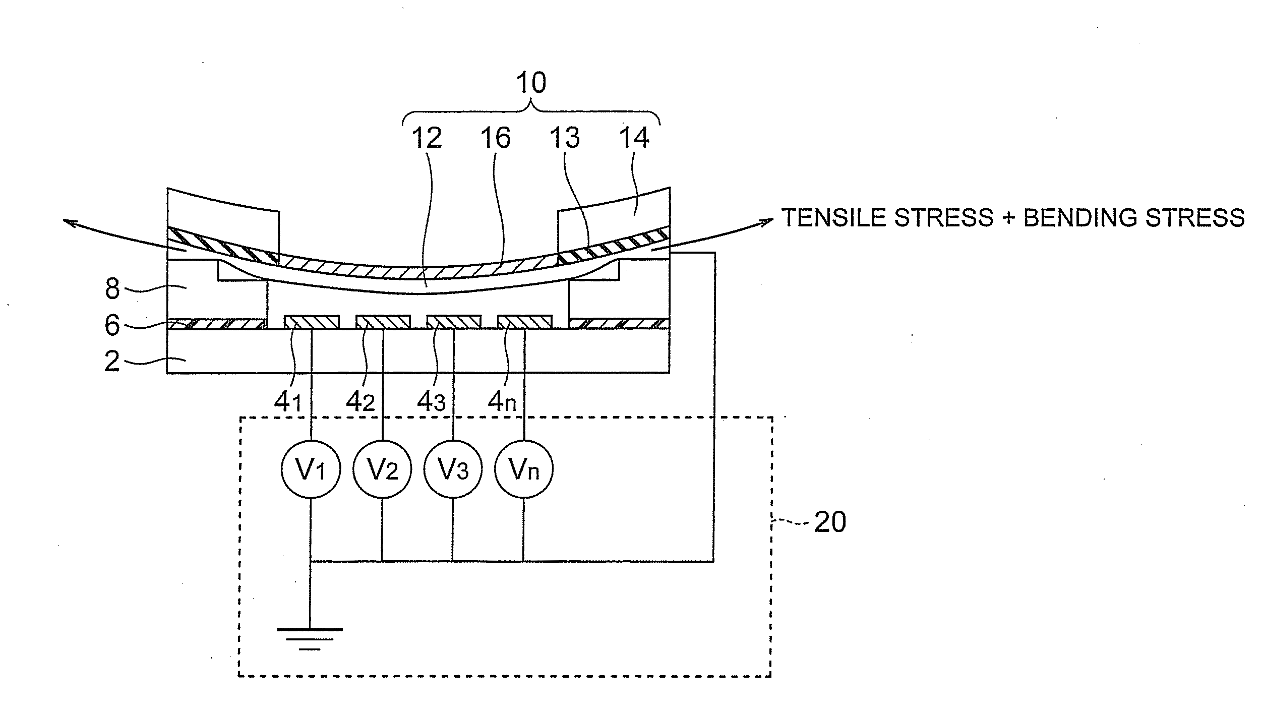
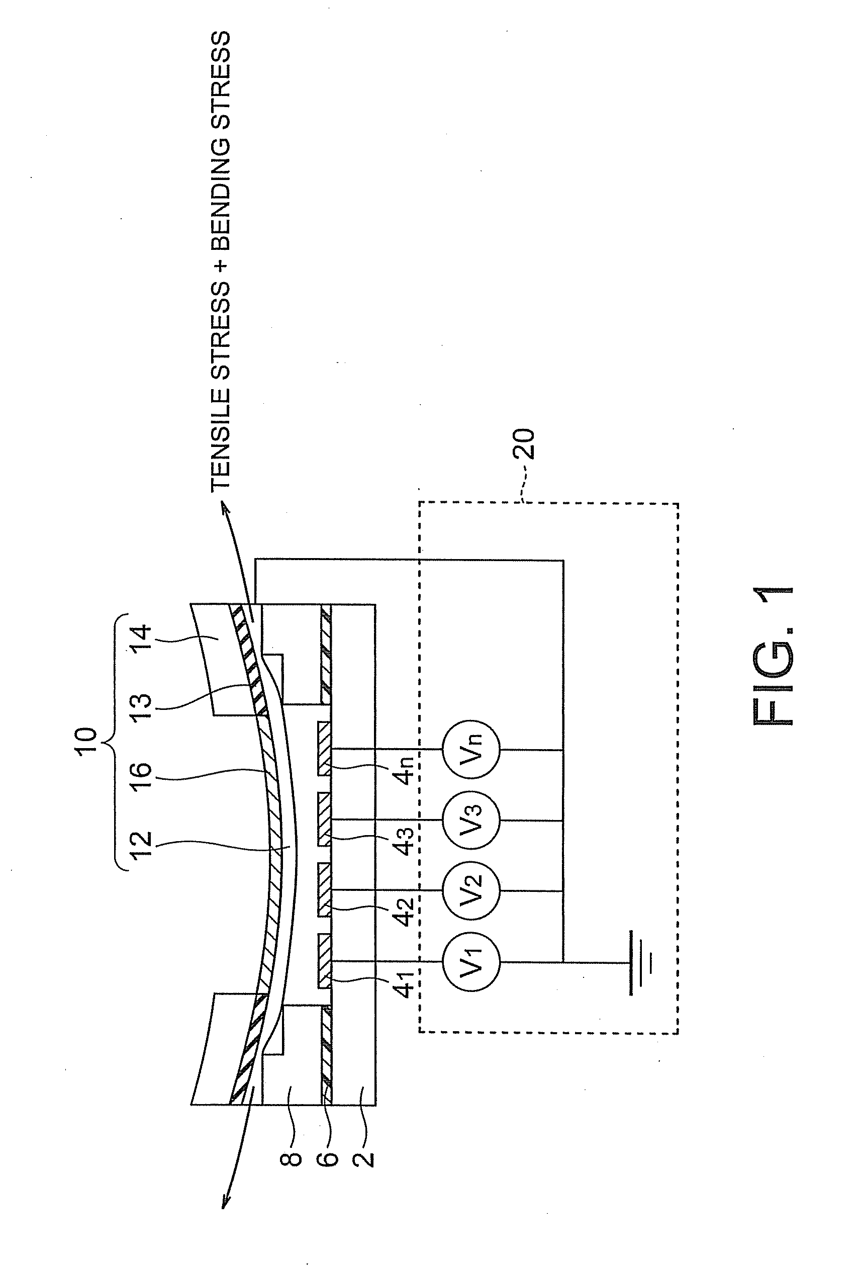
[0038]A deformable mirror apparatus according to a first embodiment of the present invention is shown in FIG. 1. In a deformable mirror apparatus according to the present embodiment, a plurality of electrodes 41 to 4n are formed on a laminated ceramic substrate 2. Furthermore, a spacer substrate 8 having an opening in its central part is provided on the laminated ceramic substrate 2. The spacer substrate 8 is bonded to the laminated ceramic substrate 2 by an adhesive agent 6 so as to dispose a plurality of electrodes 4 on the bottom part of the opening. A step (one step in FIG. 1) is provided on a surface of the spacer substrate 8 on the opposite side from the laminated ceramic substrate 2. A drive part 10 is provided on the surface of the spacer substrate 8 having the step. The drive part 10 includes a membrane part 12 disposed so as to be in contact with and cover the step and so as to be opposed to the electrodes 4, a casing part 14 which supports the membrane part 12 and which h...

second embodiment

[0060]A deformable mirror apparatus according to a second embodiment of the present invention is shown in FIG. 17.

[0061]The deformable mirror apparatus according to the present embodiment is formed by replacing the spacer substrate 8 in the first embodiment with a spacer substrate 9 (made of, for example, glass) which has a flat surface and which is smaller in thermal expansion coefficient than the membrane part 12 and the casing part 14 included in the drive part 10, and conducting anodic bonding with the drive part 10 under heating (at, for example, 350° C.). In a state in which voltages are not applied to the electrodes 41 to 4n in the deformable mirror apparatus according to the present embodiment, therefore, tensile stress and compressive stress caused by a thermal expansion coefficient difference act near the interface between the spacer substrate 9 and the membrane part 12. As a result, a change is caused in the boundary condition (fixing condition of the membrane part 12) an...

third embodiment

[0063]A deformable mirror apparatus according to a third embodiment of the present invention is shown in FIG. 18.

[0064]The deformable mirror apparatus according to the present embodiment has a configuration obtained from the configuration in the first embodiment shown in FIG. 1 by replacing the spacer substrate 8 with a spacer 7 and sticking a doughnut-shaped thin film piezoelectric actuator 40 on an opposite side of the membrane part 12 from the reflection film 16 (on a side opposed to the electrodes) or forming a film. The thin film piezoelectric actuator 40 is provided in a position where the operation of deforming the membrane part 12 by electrostatic sucking force is not interfered. By the way, the spacer 7 is bonded to the substrate 2 and the membrane part 12 by using an adhesive agent 6.

[0065]In the structure of the present embodiment, stress caused in the membrane part 12 when currents are let flow through the electrodes 41 to 4n and the membrane part 12 is calculated by usi...


PUM


Abstract

It is made possible to provide a deformable mirror apparatus which is deformable to a complicated shape (high-order shape). A deformable mirror apparatus includes: a substrate; a plurality of electrodes provided on the substrate; a spacer fixed above the substrate, having a first opening passing through from a first face of the spacer facing to the substrate to a second face of the spacer facing opposite from the first face, surrounding the electrodes, and having a step on the second face; a drive part including a membrane part disposed so as to cover the step of the spacer and so as to be opposed to the electrodes, a casing part having an opening at a bottom face of which the membrane part is exposed and supporting the membrane part, and a reflection film provided on the membrane part; and a voltage generator configured to generate predetermined voltage patterns on the electrodes, respectively.

Description

CROSS-REFERENCE TO RELATED APPLICATION[0001]This application is based upon and claims the benefit of priority from prior Japanese Patent Application No. 2007-81923 filed on Mar. 27, 2007 in Japan, the entire contents of which are incorporated herein by reference.BACKGROUND OF THE INVENTION[0002]1. Field of the Invention[0003]The present invention relates to a deformable mirror apparatus.[0004]2. Related Art[0005]In general, the eyeground observation apparatus is an apparatus which irradiates a retina of an eye to be examined with illumination light and receives and detects light of an image of the retina to be examined through a retina image forming optical system by using an image pickup device (for example, a CCD camera) to observe the retina of the eye. For detecting and preventing a disease concerning eyes, it is desirable that the detection accuracy and resolution are high as far as possible. Since an eyeball is not an ideal lens having no aberration, however, the eyeball has w...

Claims


Application Information

Patent Timeline
IPC IPC(8): G02B26/00
CPCG02B26/0825
Inventor MASUNISHI, KEIKOGA, AKIHIROFURUKAWA, RYOKUGIMIYA, TETSUYAKOBAYASHI, AKIOKAWASHIMA, HIROYUKI
Owner KK TOSHIBA
Why Eureka
Try Eureka