Cooling of High Power Density Devices Using Electrically Conducting Fluids

a high-power density device and fluid technology, applied in the field of high-power density devices, can solve the problems of permanent loss of data from memory, and achieve the effects of reducing the overall weight and cost of the heat dissipation system, high-power density devices, and facilitating heat exchang

Inactive Publication Date: 2008-10-02
ZAGORIN OBRIEN GRAHAM
View PDF50 Cites 30 Cited by
  • Summary
  • Abstract
  • Description
  • Claims
  • Application Information

AI Technical Summary

Benefits of technology

[0053]The systems of liquid metal and heat pipes described above may be used for effective heat dissipation over large distances without requiring a large amount of liquid metal. This reduces the overall weight and the cost of the heat dissipation system.
[0054]FIG. 9 shows one variation on previously described embodiments, in which liquid metal container 902 facilitates heat exchange between the liquid metal and a high power density device. Within sealed liquid metal container 902, liquid metal comes in direct contact with a high power density device, such as high power density device 202. This increases the efficiency of heat transfer to the liquid metal as there is little intermediate material between high power density device 202 and the liquid metal. The material of the surface of high power density device 202, which comes in direct contact with the liquid metal should be such that it is not corroded by the liquid metal. Exemplary materials for such a surface include copper plated with nickel, silicon dioxide and silicon coated with silicon nitride. Sealed liquid metal container 902 is sealed around the edges of high power density device 202. Sealed liquid metal container 902 could be constructed using a rigid and inert polymer (Teflon™, polyurethane, etc.), thermoplastics or metals such as copper, nickel.

Problems solved by technology

For example, in a computer, in case the heat dissipated by components such as the microprocessor or the power unit is in proximity of components like memory, this heat may lead to permanent loss of data from memory.

Method used


Image

  • Cooling of High Power Density Devices Using Electrically Conducting Fluids
  • Cooling of High Power Density Devices Using Electrically Conducting Fluids
  • Cooling of High Power Density Devices Using Electrically Conducting Fluids

Examples


Embodiment Construction

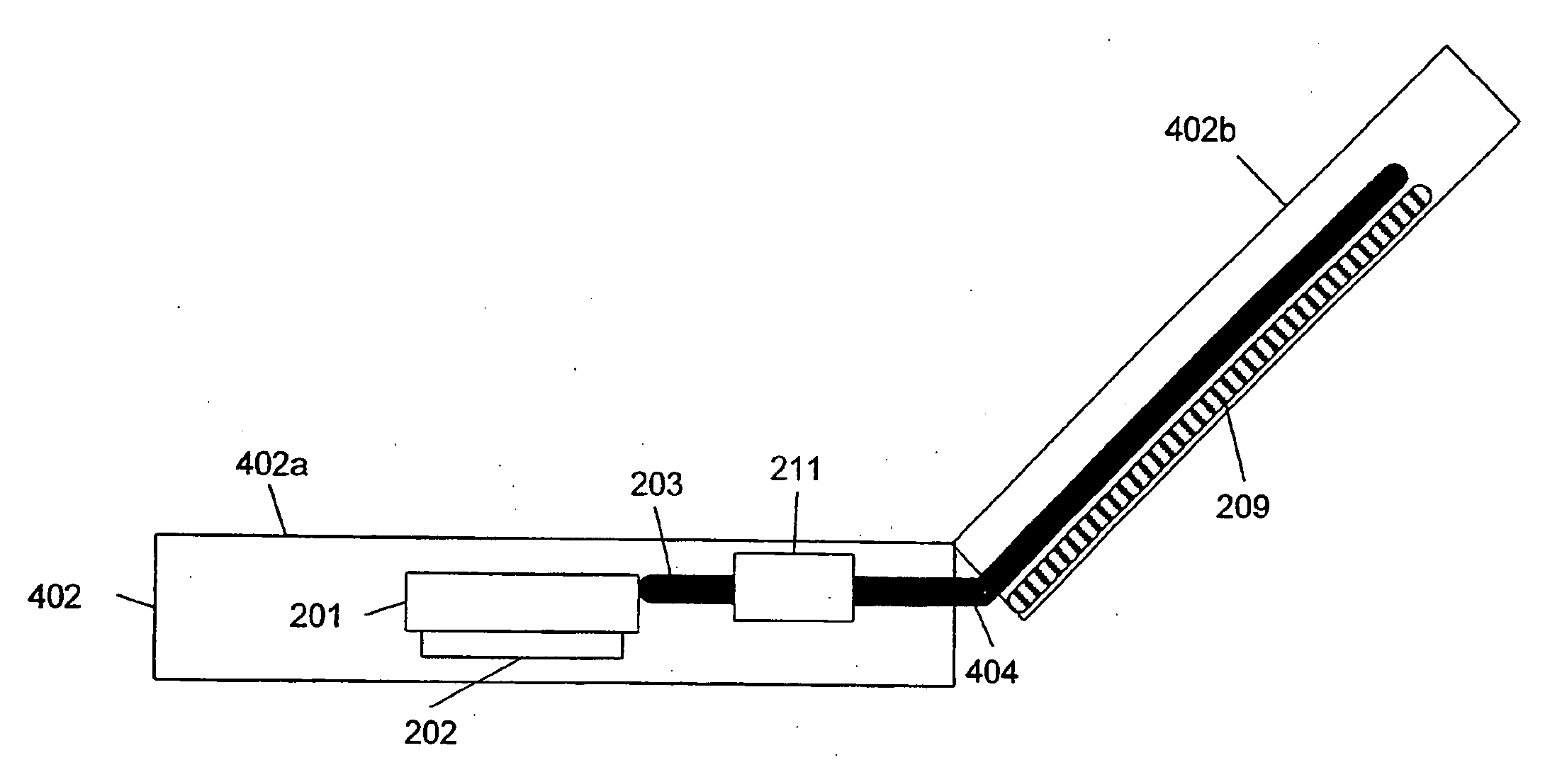
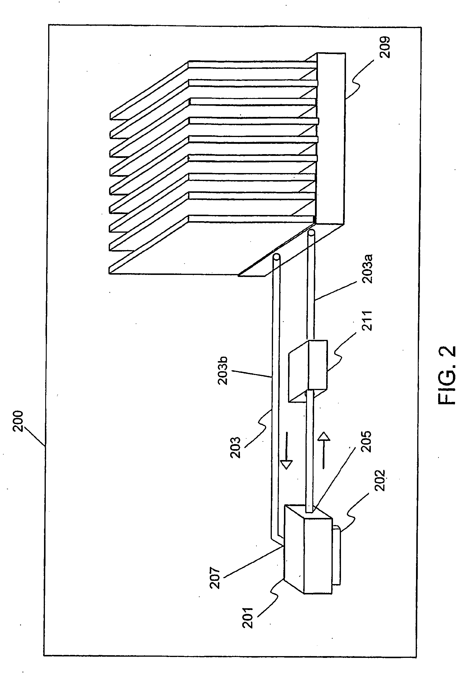
[0012]The present invention is described in terms of various embodiments that include or provide a system for effective removal of heat from a high power density device and dissipating the heat at a distance. In some embodiments in accordance with the present invention, such a system includes a liquid metal chamber mounted on a high power density device. The liquid metal chamber can include a solid-fluid heat exchanger or may allow direct contact of the liquid metal with the high power density device. A conduit circulates liquid metal through the liquid metal chamber. The liquid metal carries away the heat generated by the high power density device and dissipates it at a heat exchanger or heat sink provided at a predefined distance away from the device. This system is highly flexible and can be used in different embodiments depending on form factor and flow routing limitations. The same conduit (carrying the liquid metal) can be used for carrying heat away from multiple devices. In ...


PUM


Abstract

A system to extract heat from a high power density device and dissipate heat at a convenient distance. The system circulates liquid metal in a closed conduit using one or more electromagnetic pumps for carrying away the heat from high power density device and rejecting the heat at a heat sink located at a distance. The system may make use of a thermoelectric generator to power the electromagnetic pumps by utilizing the temperature difference between the inlet and outlet pipes of the heat sink. The system also provides networks of primary and secondary closed conduits having series and parallel arrangements of electromagnetic pumps for dissipating heat from multiple devices at a remotely located heat sink.

Description

TECHNICAL FIELD[0001]The present invention relates to a system for dissipating beat from a high power density device (HPDD). More specifically, the invention relates to a system that helps in effective dissipation of heat at a distance away from the HPDD.BACKGROUND ART[0002]Electronic devices such as central processing units, graphic-processing units, laser diodes etc. can generate significant heat during operation. If the generated heat is not dissipated properly from high power density devices, temperature buildup may occur. The buildup of temperature can adversely affect the performance of these devices. For example, excessive temperature buildup may lead to malfunctioning or breakdown of the devices. So, it is important to remove the generated heat in order to maintain normal operating temperatures of these devices.[0003]The heat generated by HPDD is removed by transferring the heat to ambient atmosphere. Several methods are available to transfer heat from a HPDD to the atmosphe...

Claims


Application Information

Patent Timeline
Patent Type & Authority Applications(United States)
IPC IPC(8): H05K7/20F25D17/02F25D23/12F28D15/00G06F1/20H01L23/473H01L35/00H02K44/02
CPCG06F1/203G06F1/206G06F2200/201H01L23/473H01L35/00H01L2924/0002H02K44/02H01L2924/00H10N10/00
Inventor GHOSHAL, UTTAMMINER, ANDREW CARL
Owner ZAGORIN OBRIEN GRAHAM
Why Eureka
Try Eureka