
Catalyst carrier and exhaust gas treatment apparatus

a technology of catalyst carrier and exhaust gas treatment apparatus, which is applied in catalyst carrier, ceramicware, separation process, etc., can solve the problems of reduced productivity, increased manufacturing cost, and increase in the number of processes

Active Publication Date: 2008-10-02
IBIDEN CO LTD
View PDF14 Cites 69 Cited by
  • Summary
  • Abstract
  • Description
  • Claims
  • Application Information

AI Technical Summary

Problems solved by technology

According to such a method, however, the porous ceramic units have considerable portions thereof cut, removed, and discarded at the time of manufacturing the ceramic block, which causes the problem of increased manufacturing costs.
Further, the number of processes increases because of the above-described process of cutting the united body, which causes the problem of reduced productivity.

Method used


Image

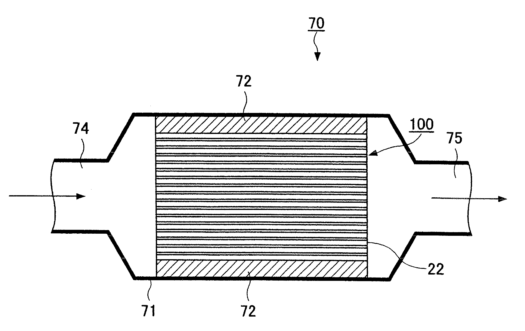
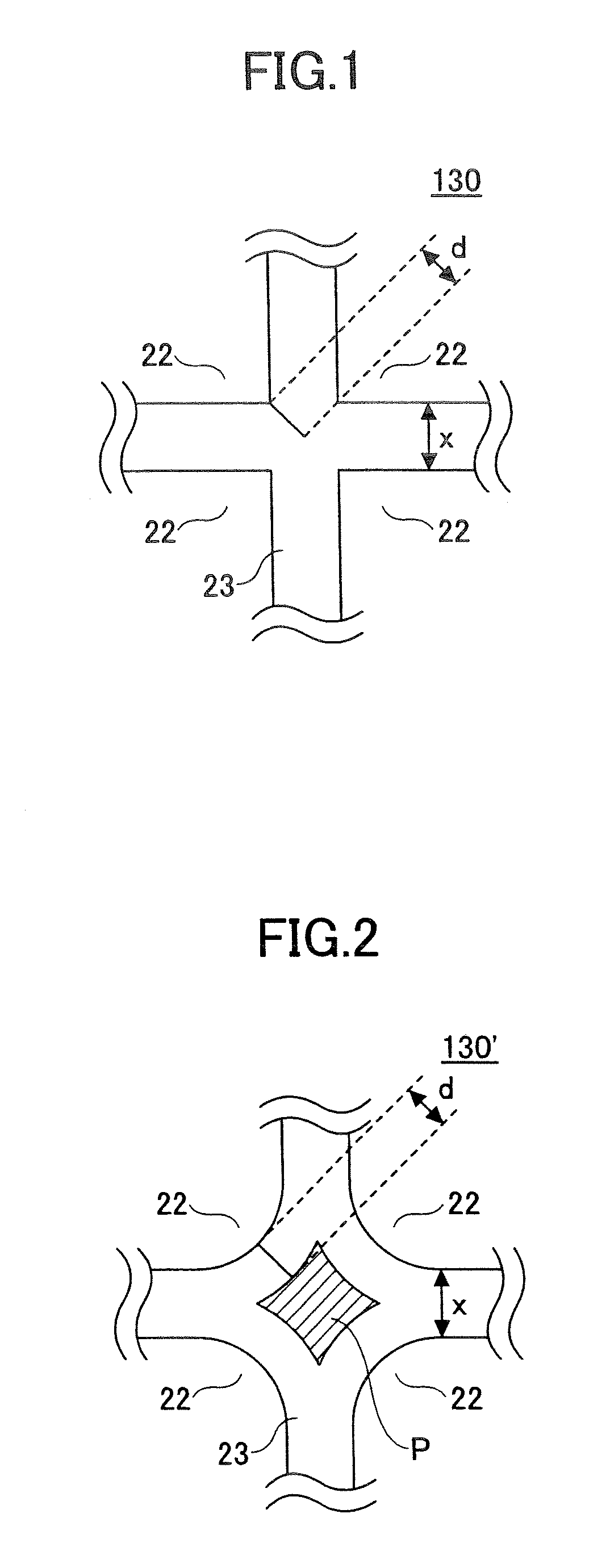
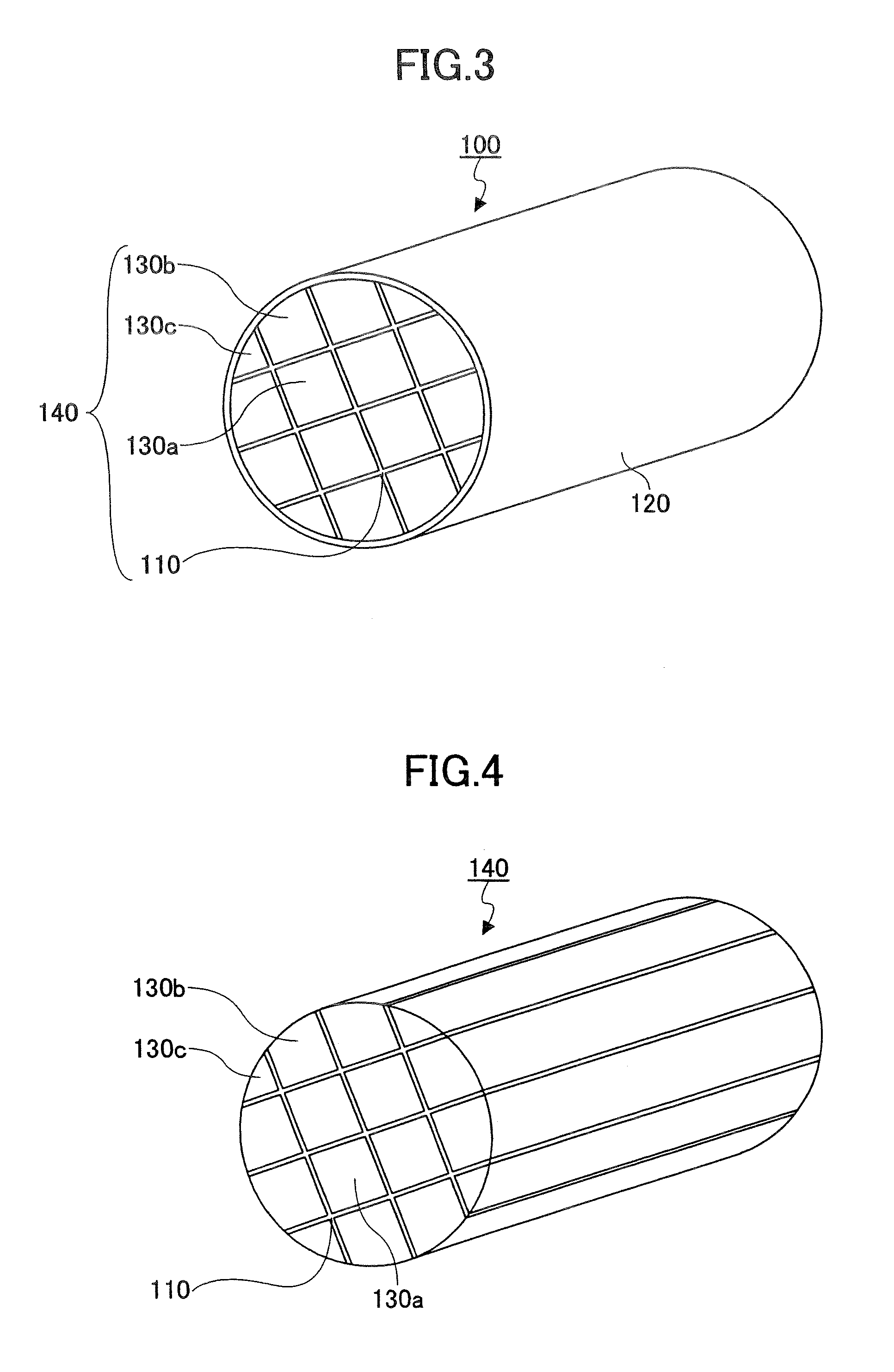
  • Catalyst carrier and exhaust gas treatment apparatus
  • Catalyst carrier and exhaust gas treatment apparatus
  • Catalyst carrier and exhaust gas treatment apparatus

Examples


example 1

Manufacture of Catalyst Carrier

[0115]First, 1575 parts by weight of γ-alumina particles (2 μm in average particle size), 675 parts by weight of zeolite, 680 parts by weight of aluminum borate whiskers, 2600 parts by weight of silica sol (of a solid concentration of 30 wt %), 320 parts by weight of methylcellulose, 225 parts by weight of a plasticizer (glycerin), and 290 parts by weight of a lubricant (UNILUB) were mixed and kneaded so that a mixture composition was obtained. Next, this mixture composition was subjected to extrusion molding with an extruder, so that molded bodies of three kinds of pillar honeycomb units shown in FIGS. 5, 7, and 8 (hereinafter referred to as first, second, and third honeycomb units, respectively) were obtained.

[0116]These molded bodies were sufficiently dried using a microwave drier and a hot air drier, and were degreased, being retained at 400° C. for 2 hours. Thereafter, the molded bodies were subjected to firing, being retained at 800° C. for 2 hou...

example 2

[0121]A catalyst carrier was manufactured by the same method as in the case of Example 1. In Example 2, however, the above-described three kinds of honeycomb units had an “outer peripheral cell wall” of 0.27 mm in thickness. The coat layer was 0.4 mm in thickness.

example 3

[0122]A catalyst carrier was manufactured by the same method as in the case of Example 1. In Example 3, however, the above-described three kinds of honeycomb units had an “outer peripheral cell wall” of 0.4 mm in thickness. The coat layer was 0.4 mm in thickness.


PUM

PropertyMeasurementUnit
thicknessaaaaaaaaaa
thicknessaaaaaaaaaa
thicknessaaaaaaaaaa

Abstract

A catalyst carrier including a ceramic block having two open faces, an outer peripheral surface, and multiple cells divided by a cell wall and extending between the open faces. The ceramic block has multiple honeycomb units combined by interposing an adhesive layer, where the honeycomb units include an outer-peripheral-side honeycomb unit and a center-side honeycomb unit combined to form the outer peripheral part and the center part, respectively, of the block. The outer-peripheral-side honeycomb unit has an outer peripheral cell wall forming the outer peripheral surface of the outer-peripheral-side honeycomb unit. The outer peripheral cell wall includes an outermost peripheral cell wall forming part of the outer peripheral surface of the block. A cell of the outer-peripheral-side honeycomb unit in contact with the outermost peripheral cell wall thereof has a corner part having a curved surface, where the corner part is on the side contacting the outermost peripheral cell wall.

Description

CROSS-REFERENCE TO RELATED APPLICATION[0001]The present application is based on PCT International Application No. PCT / JP2007 / 057254, filed on Mar. 30, 2007, the entire contents of which are hereby incorporated by reference.BACKGROUND OF THE INVENTION[0002]1. Field of the Invention[0003]The present invention relates to a catalyst carrier and an exhaust gas treatment apparatus.[0004]2. Description of the Related Art[0005]There have been proposed a variety of exhaust gas treatment apparatuses that convert harmful gases contained in exhaust gas discharged from the internal combustion engines of vehicles such as automobiles, buses, and trucks, construction machines, and the like.[0006]Common exhaust gas treatment apparatuses generally have a structure where, for example, a metal casing is provided in an exhaust pipe connected to the exhaust gas manifold of an engine and a catalyst carrier having a honeycomb structure is placed in the casing.[0007]This catalyst carrier is formed of, for e...

Claims


Application Information

Patent Timeline
Patent Type & Authority Applications(United States)
IPC IPC(8): B01D53/34
CPCB01D53/9454B01D2255/9202B01J32/00B01J35/04C04B38/0009Y10T428/24149F01N3/2853F01N2450/28F01N3/2828Y02T10/22C04B35/00Y02A50/20Y02T10/12B01J23/42B01J37/0207B01J35/56
Inventor IDO, TAKAHIKOOHNO, KAZUSHIGE
Owner IBIDEN CO LTD
Features
  • Generate Ideas
  • Intellectual Property
  • Life Sciences
  • Materials
  • Tech Scout
  • Unparalleled Data Quality
  • Higher Quality Content
  • 60% Fewer Hallucinations
Learn More