Reforming apparatus and method

a technology of gaseous hydrocarbons and apparatus, applied in the direction of solventing apparatus, energy input, manufacturing tools, etc., can solve the problems of metal dusting constant threat, inefficiency and equipment failure, corrosive degradation of alloys into dust,

Active Publication Date: 2008-10-09
MEGGIT (UK) LTD
View PDF25 Cites 51 Cited by
  • Summary
  • Abstract
  • Description
  • Claims
  • Application Information

AI Technical Summary

Benefits of technology

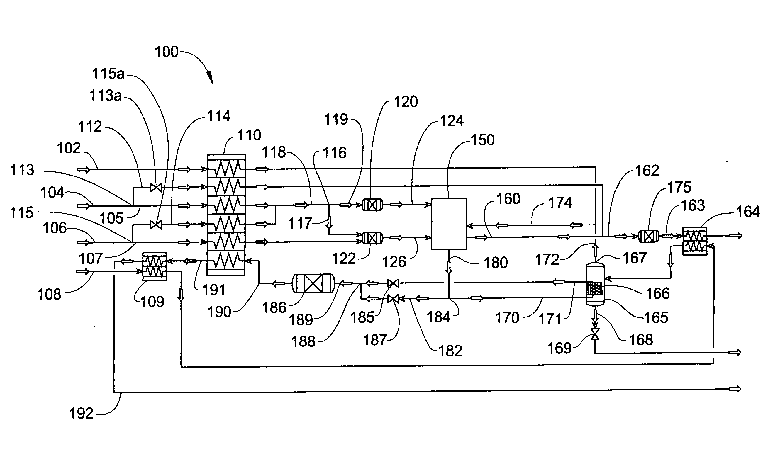
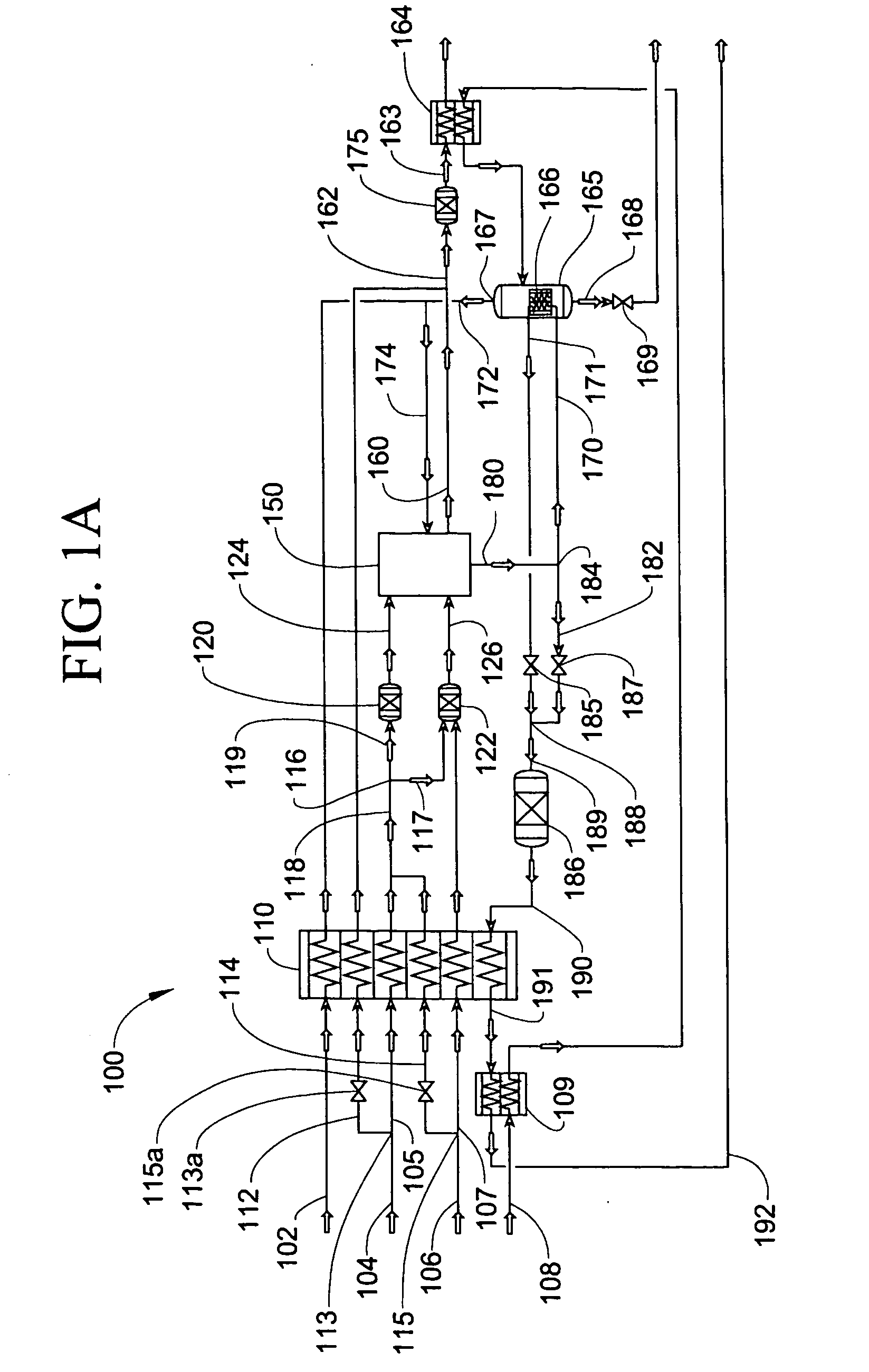
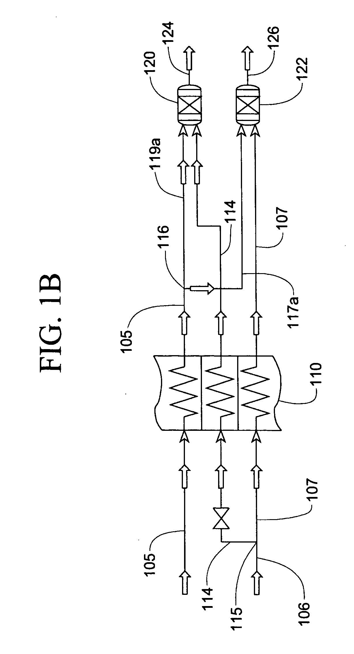
[0028]In some embodiments, the process or apparatus comprises a process or apparatus for steam reforming of gaseous hydrocarbons to produce syngas where the feed rate of the gaseous hydrocarbon is from 1 to 10,000 standard cubic meters per hour (“SCMH”). In some embodiments, the process or apparatus is configured to minimize, avoid or localize the occurrence of metal dusting and / or coking conditions throughout the steam reforming process. Preferably, the process or apparatus is configured to avoid metal dusting conditions in the heat exchangers, reforming stages and pre-reforming stages of the process or apparatus. Preferably, the process or apparatus is configured to avoid coking conditions in the fuel feed streams, in the pre-reforming and reforming stages and / or in the syngas streams.

Problems solved by technology

Two potential problems arising from the reforming reactions include metal dusting and coking, which can lead to process inefficiencies and equipment failure.
Metal dusting occurs when the combination of temperature, pressure and composition within a carbonaceous gaseous environment leads to corrosive degradation of alloys into dust.
Metal dusting conditions can be difficult to avoid in reformer systems and thus metal dusting is a constant threat.
Coking occurs when the gaseous hydrocarbons crack to produce a solid carbonaceous material which may clog or damage flow paths, which can lead to heat transfer and conversion inefficiencies and equipment failure.
Thus, the successful operation of a tubular reformer relies on maintaining a somewhat delicate balance between the endothermic reforming reactions within the tubes and the heat transfer to the tubes from the furnace combustion.
While large-scale tubular reformers have been very successful both technically and economically, small-scale tubular reformers are less successful.
Amongst other things, the costs to manufacture, install, maintain and operate tubular reformers on a smaller scale are unattractive.
Smaller users of syngas downstream products such as hydrogen, ammonia and methanol have therefore not found it attractive to establish on-site production facilities for those products.
This solution is becoming less attractive as the price of transport fuels increases.
There are considerable challenges, however: a smaller-scale system must be reasonably proportionate to large scale plant in initial cost, and operating costs must also be proportionate to the scale of production.
Importantly, whilst large-scale reforming systems might claim energy efficiency credit for the energy content of excess steam exported to other processes on the site, small-scale reforming systems are unlikely to have an export destination available for excess steam and hence its production does not enhance efficiency.

Method used


Image

  • Reforming apparatus and method
  • Reforming apparatus and method
  • Reforming apparatus and method

Examples


Embodiment Construction

[0061]In some embodiments, the process or apparatus comprises a process or apparatus for steam reforming of gaseous hydrocarbons to produce syngas where the feed rate of the gaseous hydrocarbon is from 1 to 10,000 standard cubic meters per hour (“SCMH”), such as from 2 to 5000 SCMH, such as 1 to 10, 10 to 100, 100 to 1000, 1000 to 10,000, 10 to 4000, 15 to 3000, 20 to 2000, 30 to 1000, 40 to 500, 50 to 250 or 60 to 100 SCMH.

[0062]In some embodiments, a process or apparatus for steam reforming of gaseous hydrocarbons to produce syngas, may have a hydrocarbon conversion of 50% or greater such as from 50% to 95%, such as from 55% to 90%, from 60% to 85%, from 65% to 80% or from 70% to 75%.

[0063]In some embodiments, a process or apparatus for steam reforming of gaseous hydrocarbons to produce syngas, may have an energy efficiency of from 50% to 90%, such as from 55% to 85%, from 60% to 80% or from 65% to 75% when calculated according to the following equation:

(LHVs*Ms-LHVf*Mf)LHVng*Mng[...


PUM

PropertyMeasurementUnit
heataaaaaaaaaa
pressureaaaaaaaaaa
energy efficiencyaaaaaaaaaa

Abstract

A multiple adiabatic bed reforming apparatus and process are disclosed in which stage-wise combustion, in combination with multiple reforming chambers with catalyst, utilize co-flow and cross-flow under laminar flow conditions, to provide a reformer suitable for smaller production situations as well as large scale production. A passive stage by stage fuel distribution network suitable for low pressure fuel is incorporated and the resistances in successive fuel distribution lines control the amount of fuel delivered to each combustion stage. The fuel distribution system allows relatively constant fuel and air flow during turn up or turn down conditions. High efficiency is achieved by capturing heat from reforming syngas product to preheat gases before entering the reformer. Conditions that would produce unwanted coking or metal dusting are also eliminated or localized to locations within the apparatus outside the heat exchangers, but which locations can be cost effectively protected. Also, a chemical reactor is disclosed and which has a core composed of a stack of metal plates that are diffusion bonded in face-to-face relationship. A plurality of reaction zones are located within the core, as are a plurality of catalyst receiving zones, and both the reaction zones and the catalyst receiving zones are defined by respective aligned apertures in the plates. First and second channel arrangements are provided in the plates for transporting first and second reactants to reaction zones. Portions of the first channel arrangement that interconnect the reaction zones are formed as heat exchange channels. A third channel arrangement is provided in the plates for transporting a third reactant to catalyst receiving zones. Portions of the third channel arrangement are formed as heat exchange channels in proximity to the heat exchange channels of the first channel arrangement.

Description

CROSS-REFERENCE TO RELATED APPLICATIONS[0001]This application is a continuation-in-part of U.S. patent application Ser. No. 11 / 818,916 filed Jun. 16, 2007, which is a continuation-in-part of U.S. patent application Ser. No. 10 / 500,176 filed Jan. 10, 2005, now U.S. Pat. No. 7,276,214 issued Oct. 2, 2007, which is a National Stage filing under 35 U.S.C. § 371 of International Patent Application No. PCT / AU03 / 00022 filed Jan. 3, 2003 and which claims benefit of priority to Australian Patent Application No. PR9817 filed Jan. 4, 2002, the entire contents of each of which are hereby incorporated by reference.FIELD OF THE INVENTION[0002]This invention relates to apparatuses and methods for reforming of gaseous hydrocarbons and more particularly relates to high efficiency, low metal dusting, low coking apparatuses and methods for reforming gaseous hydrocarbons.BACKGROUND OF THE INVENTION[0003]Steam reforming is a catalytic reaction in which a mixture of steam and gaseous hydrocarbons is expo...

Claims


Application Information

Patent Timeline
Patent Type & Authority Applications(United States)
IPC IPC(8): C01B3/38
CPCB01J19/249C01B2203/0216B01J2219/2458B01J2219/2465B01J2219/2475B01J2219/2477B01J2219/2497C01B3/38C01B3/48C01B2203/0233C01B2203/0288C01B2203/044C01B2203/047C01B2203/0495C01B2203/066C01B2203/0811C01B2203/0844C01B2203/0866C01B2203/0883C01B2203/1241C01B2203/143C01B2203/146C01B2203/147C01B2203/82B01J12/005C01B3/34B01J2219/2453Y02P20/129
Inventor JOHNSTON, ANTHONY M.
Owner MEGGIT (UK) LTD
Why Eureka
Try Eureka