Inertial sensor and electrical or electronic device

a sensor and inertial sensor technology, applied in the direction of turn-sensitive devices, acceleration measurement using interia forces, instruments, etc., can solve the problems of complex apparatus structure, inability to realize practical use, and inability to obtain angular velocity sensors about the three axes. to achieve the effect of simple harmonic motion, simple harmonic motion and reduced space for installing inertial sensors

Inactive Publication Date: 2008-10-09
SONY CORP
View PDF6 Cites 39 Cited by
  • Summary
  • Abstract
  • Description
  • Claims
  • Application Information

AI Technical Summary

Benefits of technology

[0011]The present invention focuses attention on a change in oscillation vector caused by application of an angular velocity. Accordingly, it is desirable to achieve measurement of angular velocities about three axes or accelerations along the three axes with a simple structure using at least one simple harmonic oscillator that oscillates along a single axis and exhibits a simple harmonic motion.
[0013]According to this embodiment of the present invention, the X, Y, and Z axes as the reference axes for detection of the oscillation direction of the oscillator are shifted to provide the x, y, and z axes, serving as new reference axes. The oscillation of the oscillator is a simple harmonic motion along the Z axis. Position coordinates of the oscillator of the x, y, and z axes are determined in at least two points during one period of the oscillator. A difference vector (Δx, Δy, Δz) is calculated on the basis of the determined position coordinates. An angular velocity or an acceleration is obtained on the basis of the difference vector. Accordingly, angular velocities about the three axes or accelerations along the three axes can be measured with a simple structure, namely, using the oscillator that oscillates along a single axis and exhibits a simple harmonic motion.
[0015]According to the embodiment first described above, angular velocities about the three axes or accelerations along the three axes can be measured with the simple structure, namely, using the oscillator that oscillates along a single axis and exhibits a simple harmonic motion. Advantageously, this embodiment provides the inertial sensor smaller than related-art inertial sensors including a plurality of angular velocity detectors.
[0016]According to the embodiment second described above, the device includes the inertial sensor according to the embodiment first described above. Advantageously, a space for installing the inertial sensor can be reduced since the inertial sensor can be miniaturized.

Problems solved by technology

Multiaxial angular velocity sensors have rarely been reported in literatures and have not been put into practical use.
Accordingly, the entire structure of an apparatus for obtaining angular velocities about the three axes is complicated and the manufacturing cost of the apparatus is expensive.
However, those controls are difficult.
Specifically, it is technically difficult to suppress noise caused by centrifugal separation and a disturbance acceleration.
Disadvantageously, it is difficult to obtain the S / N ratio equivalent to that of a related-art angular velocity sensor.
Furthermore, it is technically difficult to simultaneously provide the directions of the X and Y axes and the direction of the Z axis.

Method used


Image

  • Inertial sensor and electrical or electronic device
  • Inertial sensor and electrical or electronic device
  • Inertial sensor and electrical or electronic device

Examples


Embodiment Construction

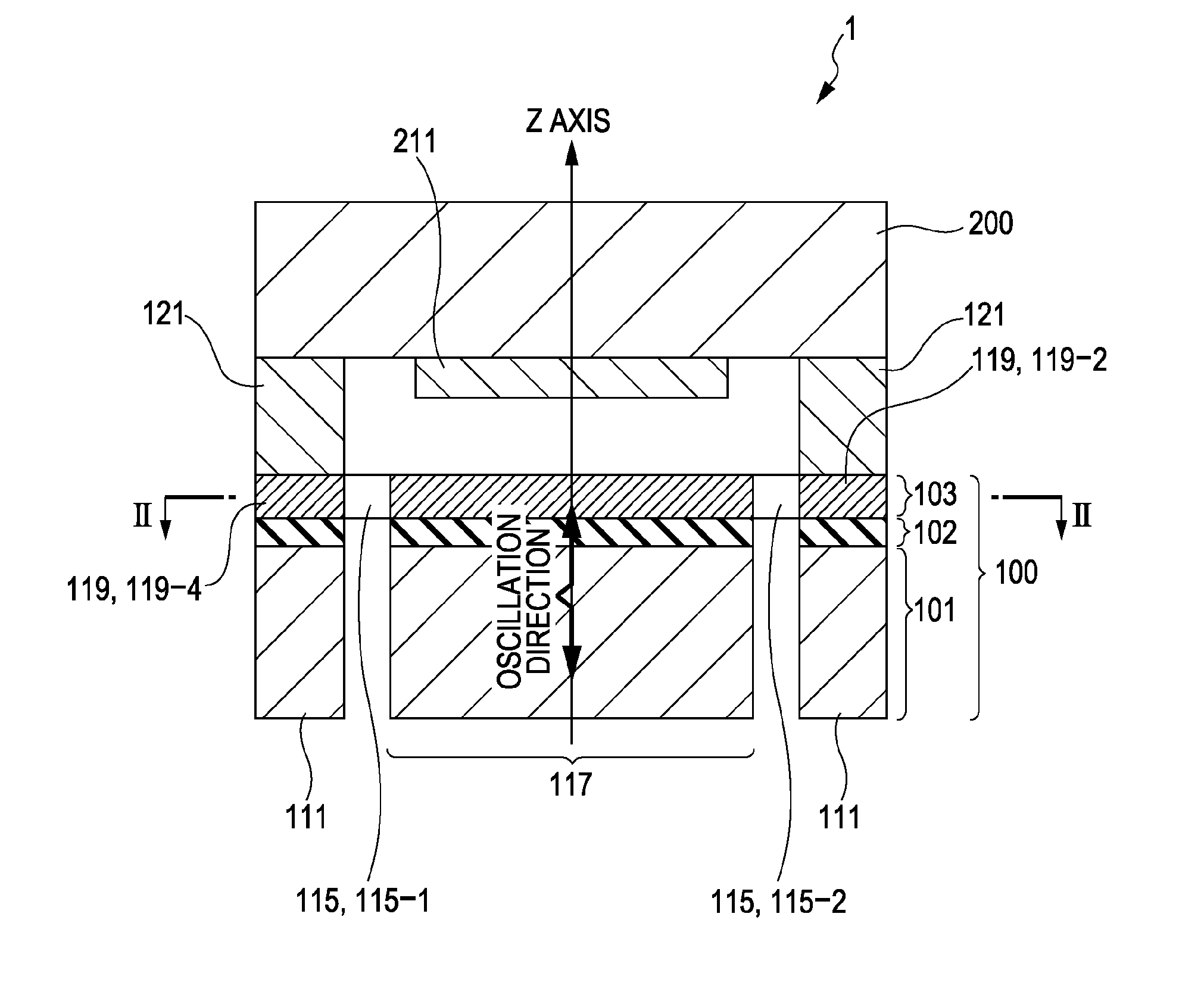
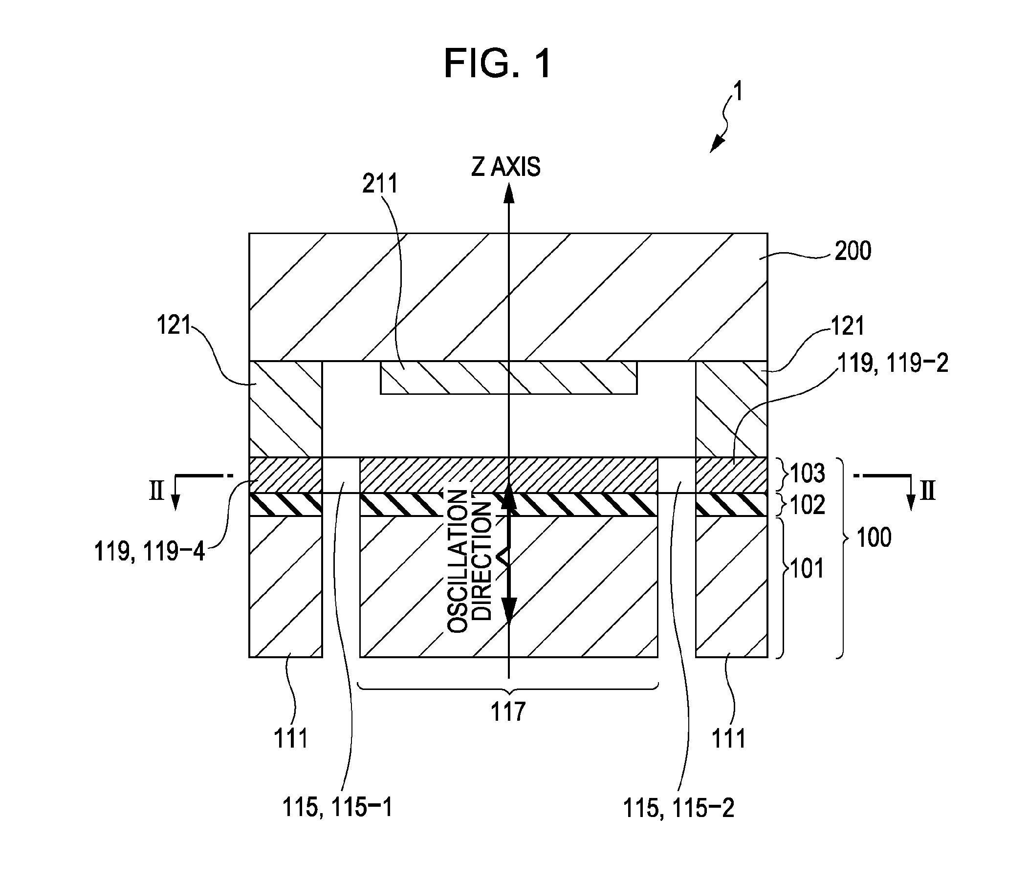
[0028]An inertial sensor according to an embodiment of the present invention will now be described with reference to FIGS. 1 and 2.

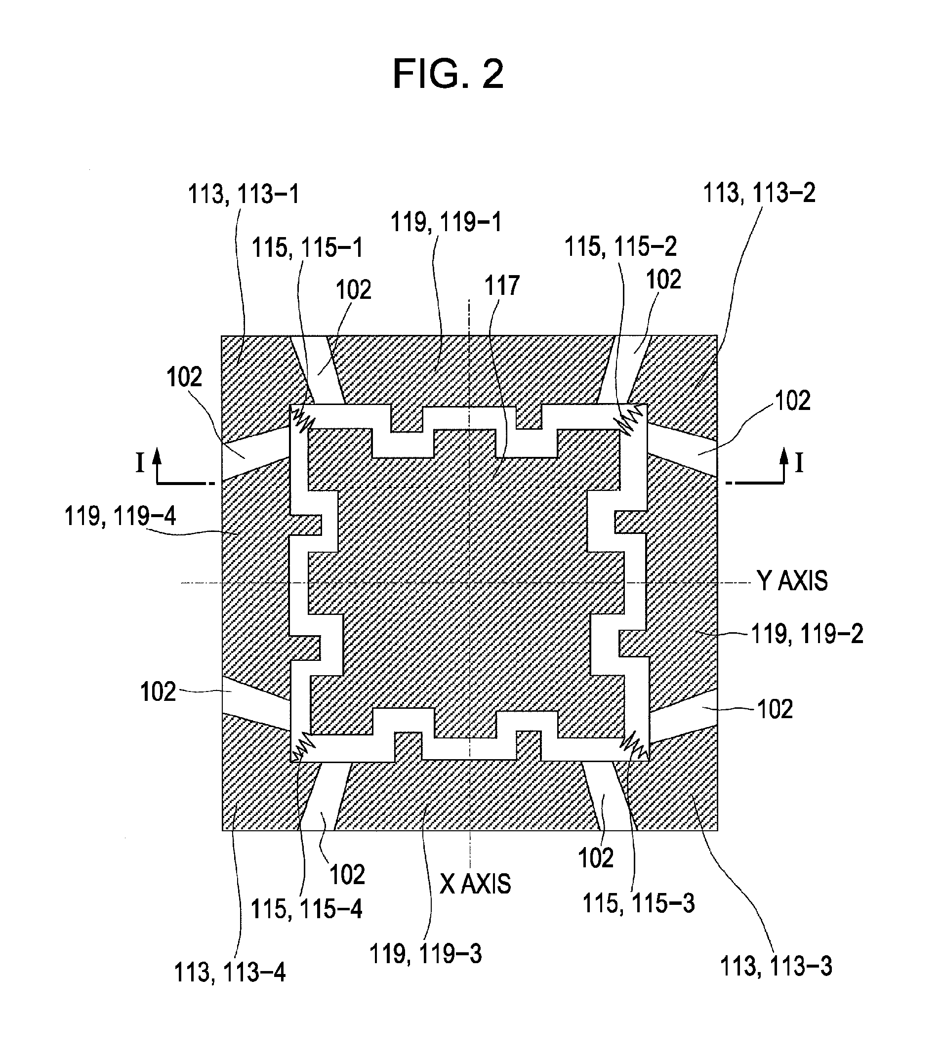
[0029]FIG. 1 is a vertical sectional view of the inertial sensor including the line I-I in FIG. 2. FIG. 2 is a transverse sectional view thereof including the line II-II in FIG. 1. In the present embodiment, the inertial sensor including an electrostatic driving type oscillator exhibiting oscillation along a single axis will be explained as an example.

[0030]Referring to FIGS. 1 and 2, supports 113 (113-1 to 113-4) are arranged on a frame base 111. The base 111 is composed of, for example, a silicon substrate 101. The supports 113, composed of a silicon layer 103, are arranged at, for example, the respective corners of the base 111 with an insulating layer 102 therebetween. The supports 113 support an oscillator 117 through respective elastic supporting members 115 (115-1 to 115-4) so that the oscillator 117 can exhibit simple harmonic motion along a Z ax...


PUM


Abstract

An inertial sensor includes an oscillator that is supported by an elastic supporting member such that the oscillator is floating relative to a base and the oscillator is displaceable along a single axis, and a displacement detection unit detecting a displacement of the oscillator. The oscillation of the oscillator is a simple harmonic motion along a Z axis. An X axis, a Y axis, and the Z axis, serving as reference axes of an oscillation coordinate system for the oscillator, are shifted to provide x, y, and z axes, serving as new reference axes. Position coordinates of the oscillator of the x, y, and z axes are determined in at least two points during one period of the oscillator. A difference vector (Δx, Δy, Δz) is calculated on the basis of the determined position coordinates. An angular velocity or an acceleration is obtained using the difference vector.

Description

CROSS REFERENCES TO RELATED APPLICATIONS[0001]The present invention contains subject matter related to Japanese Patent Application JP 2007-097179 filed in the Japanese Patent Office on Apr. 3, 2007, the entire contents of which are incorporated herein by reference.BACKGROUND OF THE INVENTION[0002]1. Field of the Invention[0003]The present invention relates to an inertial sensor that measures angular velocities about three axes and accelerations along the three axes and relates to an electrical or electronic device including the inertial sensor.[0004]2. Description of the Related Art[0005]In automobile and mechanical industries, there is a growing demand for sensors capable of accurately measuring a physical quantity, such as an acceleration or an angular velocity. In general, an object that moves freely in a three-dimensional space is acted upon by an acceleration in any direction and an angular velocity in any rotation direction. To accurately grasp the motion of the object, it is ...

Claims


Application Information

Patent Timeline
Patent Type & Authority Applications(United States)
IPC IPC(8): G01C19/56G01P15/18
CPCG01P15/18G01C19/5719G01P15/02
Inventor FUKUMOTO, KOJI
Owner SONY CORP
Why Eureka
Try Eureka