REFERENCE NUMBERS IN DRAWINGS
[0014] 1 magnetically susceptible transducer core [0015] 2 electrically conductive coil disposed on core 1 [0016] 3 gap in core 1 [0017] 3′ gap in core 1 [0018] 4 magnetically susceptible string [0019] 4′ magnetically susceptible string [0020] 5 permanent magnet [0021] 5′ permanent magnet [0022] 6 magnetically susceptible magnetizing core [0023] 7 electrically conductive coil disposed on 6
SUMMARY
[0024]The invention is a novel electromagnetic transducer employing specially shaped magnetically susceptible cores and/or permanent magnets in order to contain and guide magnetic flux.
DESCRIPTION OF INVENTION FIGS. 1 TO 5
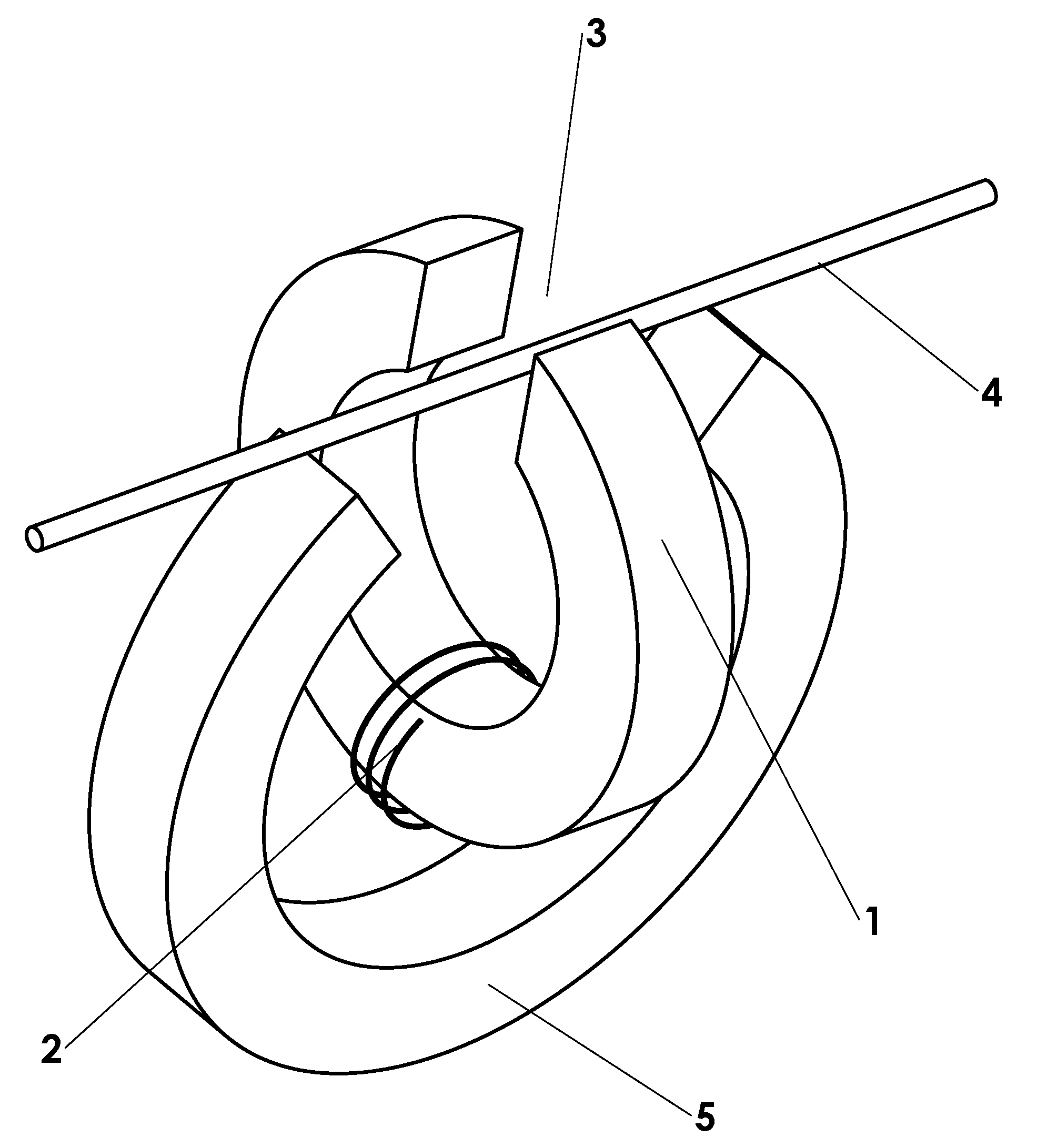
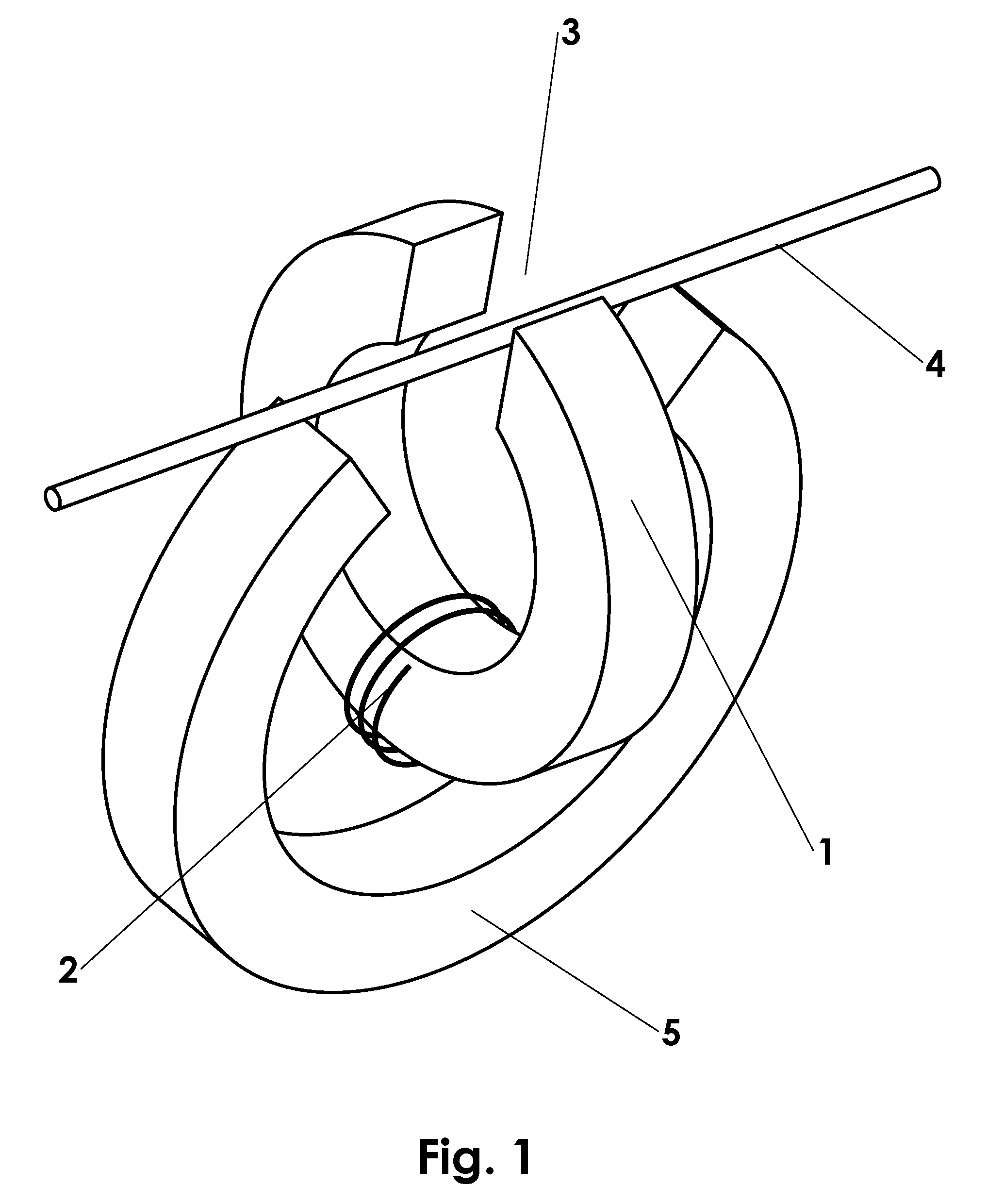
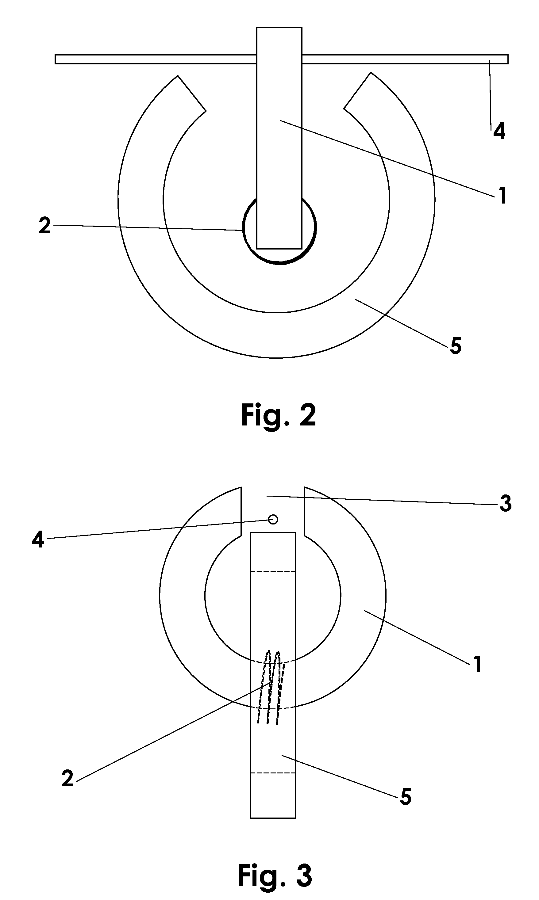
[0025]A basic embodiment of the electromagnetic transducer of the invention is shown in FIG. 1-3. Fundamentally, the transducer consists of a magnetically susceptible transducer core 1 upon which one or more turns of an electrically conductive coil 2 are wound. Core 1 is shaped such that it provides a closed path for magnetic flux everywhere except a gap 3 in which a magnetically susceptible string 4 is present. In its preferred embodiment, core 1 would be essentially ring-shaped with gap 3 for the string. In order to drive magnetic flux lengthwise through string 4, it is necessary to provide a permanent magnet 5. This magnet is also shaped in such a way that it provides a closed path for magnetic flux everywhere except the area in which the flux is driven into string 4. Again, the preferred embodiment of this magnet would be ring shaped with a section cut out so the magnetic flux is driven into string 4.
[0026]FIG. 4 shows an alternative embodiment in which a single such electromagnetic transducer is used for a plurality of strings 4 and 4′ by placing a plurality of gaps 3 and 3′ in core 1. In this configuration, it would be necessary to provide each string with a means of driving magnetic flux lengthwise, such as permanent magnets 5 and 5′. It would also be possible to put more than one string in a single gap for double-strung instruments, such as mandolins. In this configuration a plurality of strings tuned to a single pitch could share a means of driving magnetic flux since the strings of each course on double-strung instruments are very close together.
[0027]FIG. 5 shows an alternative embodiment that uses no permanent magnets. Instead of permanent magnet 5, one could employ a magnetically susceptible core 6, about which one or more turns of an electrically conductive coil 7 are wound to drive longitudinal magnetic flux in the string. Again, in its preferred embodying, this core is ring shaped with a section cut out so magnetic flux is driven on magnetically susceptible string 4.
[0028]Although not shown in the drawings for clarity of mechanical detail, the electromagnetic transducer elements should be encased in some sort of protective coating, such as a plastic. This casing is essential in order to protect the assembly from eventual corrosion due to contact with human hands. Naturally, a support structure and means of adjusting the spatial location of the individual components of the transducer subassembly would be provided in any commercial embodiment.
Operation FIG. 1
[0029]When string 4 vibrates mechanically, the longitudinal magnetic field that is driven through the string by magnet 5 also vibrates. This vibration of the magnetic field drives magnetic flux through core 1 via gap 3. The magnetic flux driven through core 1 induces a current to flow in coil 2 on the core. The current flowing in coil 2 will be of the same harmonic content as the vibration of the string. This current can be amplified and reproduced electronically.
CONCLUSIONS, RAMIFICATIONS, AND SCOPE OF INVENTION
[0030]Thus, it can be seen that the nearly closed magnetic flux electromagnetic transducer of the invention is a simple, economical, and efficient device to convert the mechanical vibration of a magnetically susceptible string into an electric signal. Additionally, the method of operation of this transducer provides a significant advantage of prior art by providing a transducer that, due to its efficiency, reproduces very little noise and is simple to manufacture. The transducer of this invention also makes reproducing the sound of each individual string in a single plane simple and allows the designer to tailor the frequency response of each transducer to the individual string that it is designed to reproduce. This transducer will also interface easily with digital systems for the reasons previously laid out. This transducer makes the electrification of instruments that use many strings simple since a pickup made of these transducer subassemblies scales in direct proportion to the number of strings. The transducer of this invention can also be configured into a pickup system that is backward compatible with traditional amplification and recording equipment because the signals of each individual transducer can be easily combined or aggregated into the single electric feed found on most existing electrified musical equipment.
[0031]Although this description of the invention is quite specific, this should not be construed as limiting the scope of the invention, but rather as providing an example of one preferred embodiment thereof. Many variations of the invention are possible. For example, it might prove more economical to use a magnetically susceptible core that is not perfectly rounded due to manufacturing difficulties or difficulty in mounting to the instrument. A variety of anti-corrosive coatings might be applied to the various parts of the transducer in order to increase its lifetime and comfort of use. Various means can be used to configure individual transducers into a pickup system for an instrument. Aggregation or combining of the signals from individual transducers can likewise be accomplished with a variety of means. Each element of the pickup might be provided with a means of adjusting its position relative to the other pickup elements in order to optimize efficiency and musical tone.
[0032]Accordingly, the scope of the invention should not be determined by the embodiments illustrated but rather by the appended claims and their legal equivalents.