
Vehicular system capable of suitably controlling engine speed and gear ratio according to battery charge state

a technology of vehicle and battery charge state, applied in the field of vehicle system, can solve the problems of increasing the amount of electric power generated, rapid increase or decrease of the rotational speed of the engine, and the output power of the engine is not suitably decreased, so as to achieve sufficient power supply, increase the rotational speed of the engine, and increase the amount of electric power

Inactive Publication Date: 2008-10-09
DENSO CORP
View PDF28 Cites 16 Cited by
  • Summary
  • Abstract
  • Description
  • Claims
  • Application Information

AI Technical Summary

Benefits of technology

[0011]With the above configuration, when there is a decrease in the SOC of the battery, the first control apparatus informs the second control apparatus of the decrease in the SOC of the battery. Consequently, the second control apparatus can take measures in a timely manner to prevent the battery from running down. Further, the first control apparatus sets the target charge current for recovering the decreased SOC of the battery, and controls the electric generator to increase the amount of the electric power generated by the electric generator, thereby supplying the battery with the set target charge current. Consequently, the power generation torque of the electric generator can be prevented from excessively increasing; thus, any rapid increase or decrease in the rotational speed of the engine can be accordingly prevented. As a result, the running performance of the vehicle can be secured without worrying the driver of the vehicle uncomfortable.
[0013]With the above configuration, it is possible to increase the rotational speed of the engine and thus the amount of the electric power generated by the electric generator while keeping both the output power and rotational speed of the drive shaft constant.
[0015]With the above configuration, it is possible to suitably change the rotational speed of the engine and the gear ratio of the CVT according to the SOC of the battery, thereby quickly recovering the decreased SOC of the battery.
[0017]Otherwise, one of the first and second control apparatus may preferably further include means for estimating, before the increase in the amount of the electric power generated by the electric generator, the power generation toque of the electric generator after the increase in the amount of the electric power; the second control apparatus may correct the set amounts of the increases in the rotational speed of the engine and the gear ratio of the CVT based on the estimated power generation torque of the electric generator. Further, the estimating means may estimate the value of the power generation torque of the electric generator based on rotational speed of the electric generator, field current of the electric generator, and output voltage of the electric generator; the setting means may set the target charge current of the battery according to the rotational speed, field current, and output voltage of the electric generator.
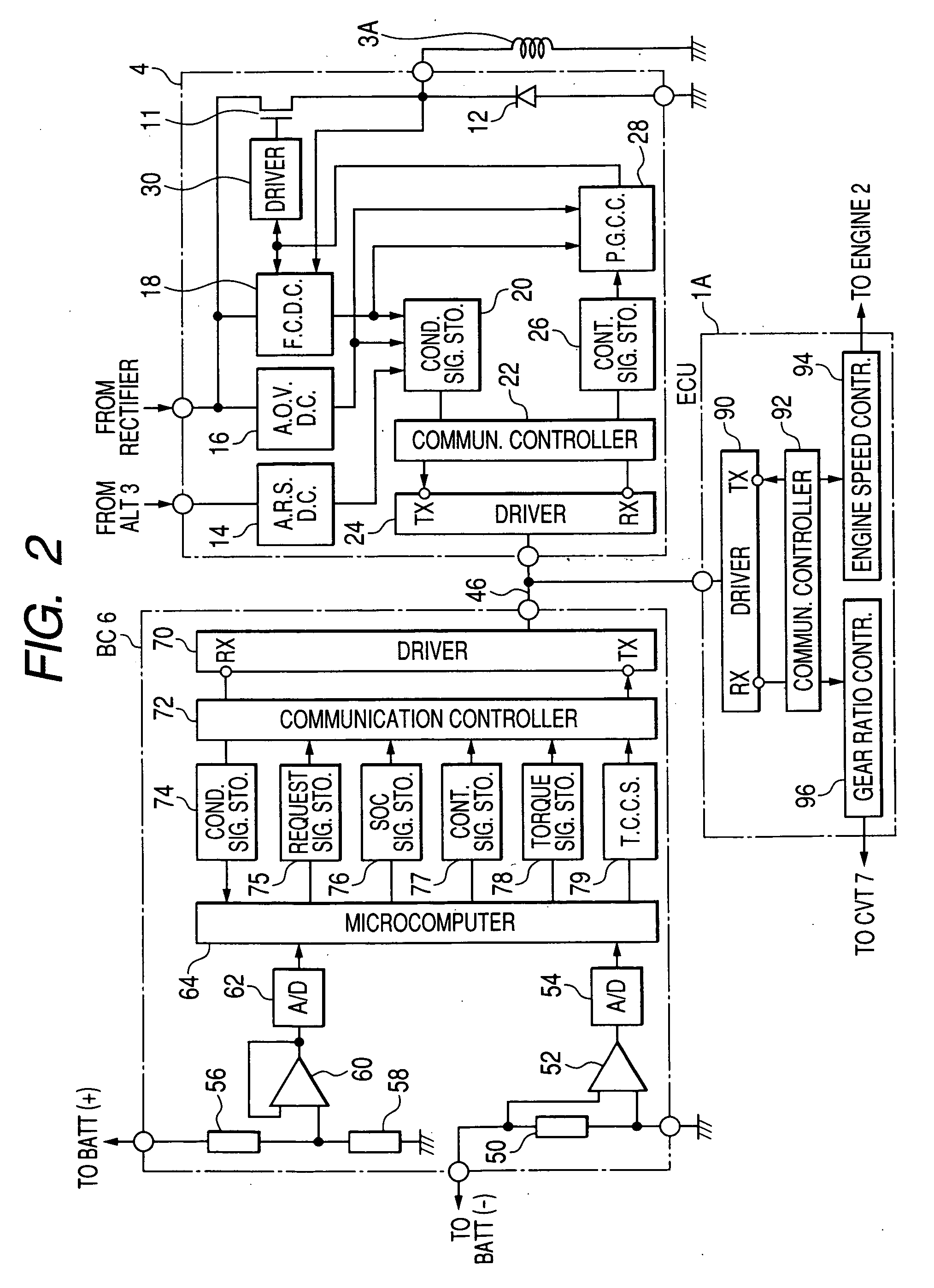
[0019]With the above configuration, it is possible to reduce the process load on the second control apparatus and minimize the total length of wire necessary for electrical connection in the vehicular system.
[0021]With the above configuration, when the battery is deteriorated, the second control apparatus can be informed of the deterioration of the battery. Consequently, the second control apparatus can increase the rotational speed of the engine to increase the amount of the electric power generated by the electric generator, thereby ensuring sufficient power supply to the electric loads on the vehicle despite the deterioration of the battery.

Problems solved by technology

With such a configuration, when the electric power consumption of the vehicle increases, the apparatus can increase the rotational speed of the engine, thereby increasing the amount of the electric power generated by an automotive alternator which charges the battery.
However, with the above configuration, when the power generation torque of the alternator increases with the amount of the electric power generated by the alternator, but the output power of the engine is not suitably decreased, a rapid increase or decrease will be caused in the rotational speed of the engine.
As a result, the running performance of the vehicle will be lowered, thus inconveniencing the driver of the vehicle.
As a result, a battery, which is configured to be charged by the alternator, can no longer be charged by the alternator, thus eventually running down.

Method used


Image

  • Vehicular system capable of suitably controlling engine speed and gear ratio according to battery charge state
  • Vehicular system capable of suitably controlling engine speed and gear ratio according to battery charge state
  • Vehicular system capable of suitably controlling engine speed and gear ratio according to battery charge state

Examples


Embodiment Construction

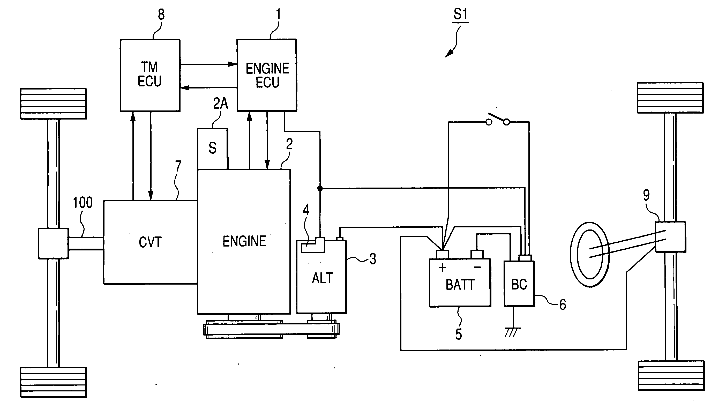
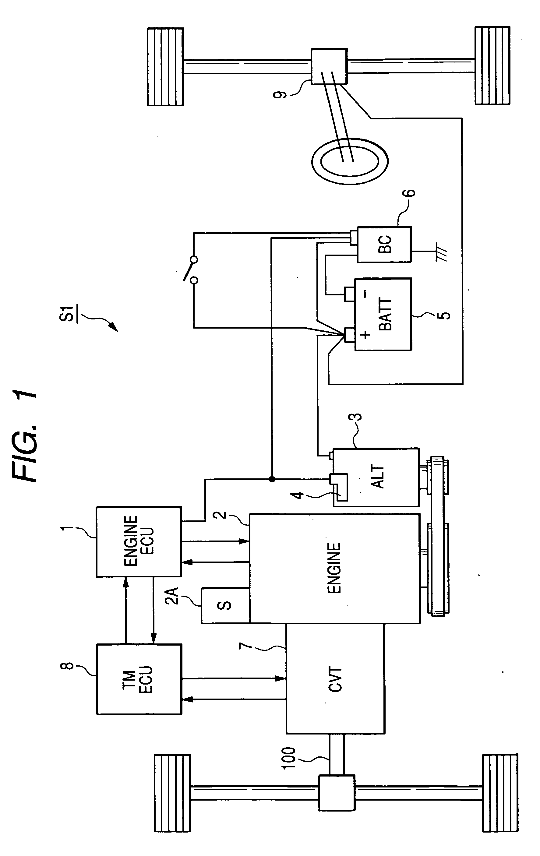
[0033]FIG. 1 shows the overall configuration of a vehicular system S1 according to an embodiment of the present invention, which is used in a motor vehicle.

[0034]As shown FIG. 1, the vehicular system S1 includes an engine ECU (Electronic Control Unit) 1, an internal combustion engine 2, an automotive alternator 3 (denoted by ALT in FIG. 1), a battery 5 (denoted by BATT in FIG. 1), a battery charge / discharge control apparatus 6 (denoted by BC in FIG. 1), a Continuously Variable Transmission (CVT) 7, a transmission ECU 8 (denoted by TM ECU in FIG. 1), an electric power steering apparatus 9, and a drive shaft 100.

[0035]The engine ECU 1 controls the operation of the engine 2.

[0036]The alternator 3 is driven by the engine 2 via a belt to generate electric power. The generated electric power is used to charge the battery 5 and power various electric loads on the vehicle. The alternator 3 includes a built-in power generation control apparatus 4, which regulates the output voltage of the al...


PUM


Abstract

A vehicular system includes a battery, an engine, an electric generator that is driven by the engine to generate electric power and thereby charge the battery, a first control apparatus that controls the battery and electric generator, a drive shaft, a CVT that transmits rotation of the engine to the drive shaft, and a second control apparatus that controls the engine and CVT. Further, the first control apparatus includes: means for detecting charge / discharge current of the battery; means for monitoring the SOC of the battery; means for informing, when there is a decrease in the SOC of the battery, the second control apparatus of the decrease in the SOC; means for setting a target charge current of the battery for recovering the decreased SOC; and means for controlling the electric generator to increase the amount of the electric power, thereby supplying the battery with the target charge current.

Description

CROSS-REFERENCE TO RELATED APPLICATION[0001]This application is based on and claims priority from Japanese Patent Application No. 2007-100082, filed on Apr. 6, 2007, the content of which is hereby incorporated by reference in its entirety into this application.BACKGROUND OF THE INVENTION[0002]1. Technical Field of the Invention[0003]The present invention relates to a vehicular system that is for use in a motor vehicle, such as a passenger car or a truck, and is configured to control the rotational speed of an engine and the gear ratio of a transmission according to the State of Charge (SOC) of a battery.[0004]2. Description of the Related Art[0005]There is known, for example from Japanese Patent First Publication No. H5-124460, a powertrain control apparatus for use in a motor vehicle. This apparatus is configured so that when the SOC of a battery drops below a predetermined threshold, the apparatus changes the gear ratio of a transmission so as to increase the rotational speed of t...

Claims


Application Information

Patent Timeline
IPC IPC(8): F02D35/00H02J7/16F02D29/06H02P9/06B60W10/10B60W10/26B60L11/18B60R16/03B60R16/04
CPCB60W10/06B60W10/08B60W10/101Y10T477/619B60W20/00Y02T10/6286B60W10/26Y02T10/62B60W10/10B60W10/04B60W2710/244B60W2510/0638
Inventor ASADA, TADATOSHI
Owner DENSO CORP
Learn More