Capacitor with improved volumetric efficiency and reduced cost

US20080247122A1Inactive Publication Date: 2008-10-09VISHAY SPRAGUE

Image

  • Capacitor with improved volumetric efficiency and reduced cost
  • Capacitor with improved volumetric efficiency and reduced cost

Examples


Embodiment Construction

[0029]For a better understanding of the present invention, an exemplary embodiment will now be described in detail. Frequent reference will be taken to the above-described drawings. Reference numerals and / or letters will be used to indicate certain parts or locations in the drawings. The same reference numerals and / or letters will be used to indicate the same parts or locations throughout the drawings unless otherwise indicated.

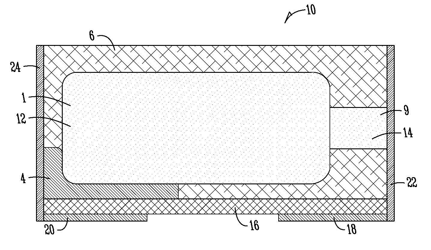
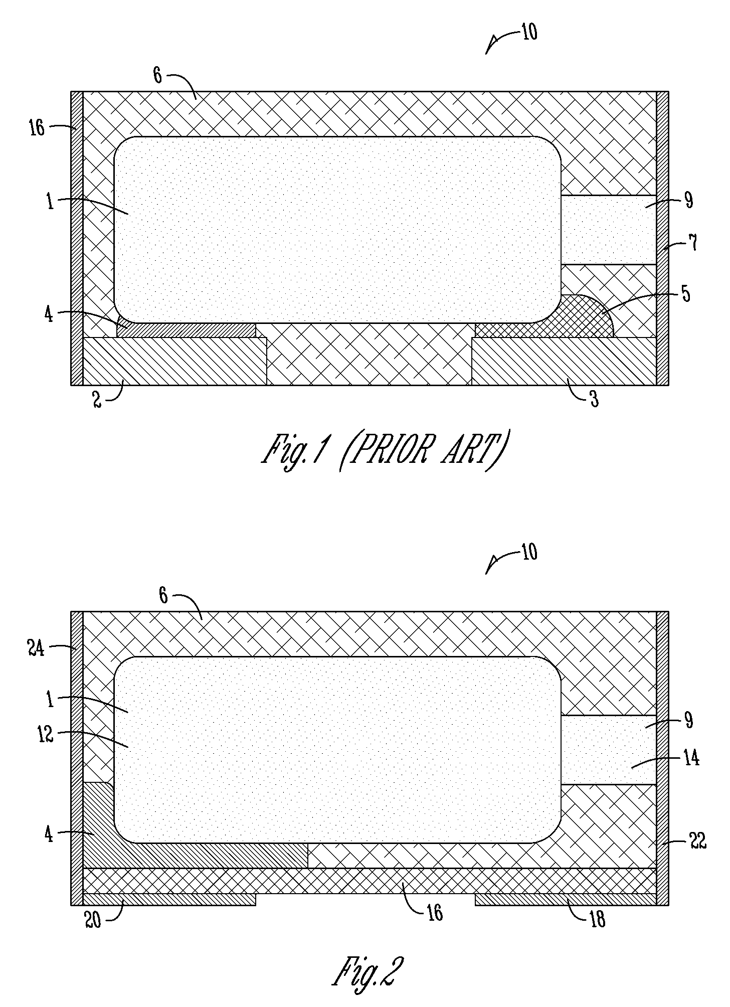
[0030]The context of this exemplary embodiment is a surface mount capacitor having single-sided terminations-anode and cathode terminations are both in generally the same plane on only one side (here the bottom surface mount side) of the device. In particular, this exemplary embodiment is a surface mount molded solid electrolyte tantalum capacitor having anode and cathode terminations on the bottom plane of the casing. The casing size of this example, case size 0603 (such as is known in the art), is relatively small (approximate dimensions: length of 1.6 (±0....


PUM

PropertyMeasurementUnit
Thicknessaaaaaaaaaa
Dielectric polarization enthalpyaaaaaaaaaa
Electrical conductivityaaaaaaaaaa

Abstract

A surface mount capacitor is provided. The surface mount capacitor includes a capacitive element including an anode and a cathode, the anode having an exposed portion, an encapsulation material partially surrounding the capacitive element, a non-conductive substrate in contact with the encapsulation material, an anode termination connected to the non-conductive substrate, a cathode termination connected to the non-conductive substrate, and a first conductive path between the exposed portion of the anode and the anode termination comprising a first external conductive connection on a first external surface of the capacitor. The capacitor may also include a second conductive path between the cathode and the cathode termination. The second conductive path includes a second external conductive connection on a second external surface of the capacitor. The second conductive path may further include a conductive adhesive between the cathode and the second external conductive connection.

Description

CROSS-REFERENCE TO RELATED APPLICATIONS[0001]This application claims priority under 35 U.S.C. §119 of a provisional application Ser. No. 60 / 910,556 filed Apr. 6, 2007, which application is hereby incorporated by reference in its entirety.BACKGROUND OF THE INVENTION[0002]The present invention relates to surface mount capacitors and, in particular to surface mount capacitors having improved volumetric efficiency and reduced cost.[0003]Demand has steadily increased for surface mount capacitors. They are useful for numerous and widely-varying applications and functions. For example, they are useful for maintaining signal integrity and high speed delivery of charge in electrical and electronic components or devices. They are also particularly useful in switching functions. They are useful for bulk decoupling capabilities to smooth transient requirements seen by a power source.[0004]The types and configurations presently available are numerous. Most have some type of capacitive element in...

Claims


Application Information

Patent Timeline
09 Oct 2008
Publication
US20080247122A1
IPC
H01G4/228; H01G9/08; H01G9/15
CPC
H01G2/065; Y10T29/417; H01G9/15; H01G9/012
Inventors
VAISMAN, PAVEL; EIDELMAN, ALEX