Ablation Devices with Sensor Structures

a sensor and ablation device technology, applied in the field of apparatus and methods for cardiac ablation and to sensor structures, can solve the problems of limiting the placement of electrodes, the configuration of the transducer array and associated structures, and the difficulty of making the device collapse to a small diameter, and achieves the effect of facilitating introduction

Active Publication Date: 2008-10-09
BOSTON SCI SCIMED INC
View PDF23 Cites 98 Cited by
  • Summary
  • Abstract
  • Description
  • Claims
  • Application Information

AI Technical Summary

Benefits of technology

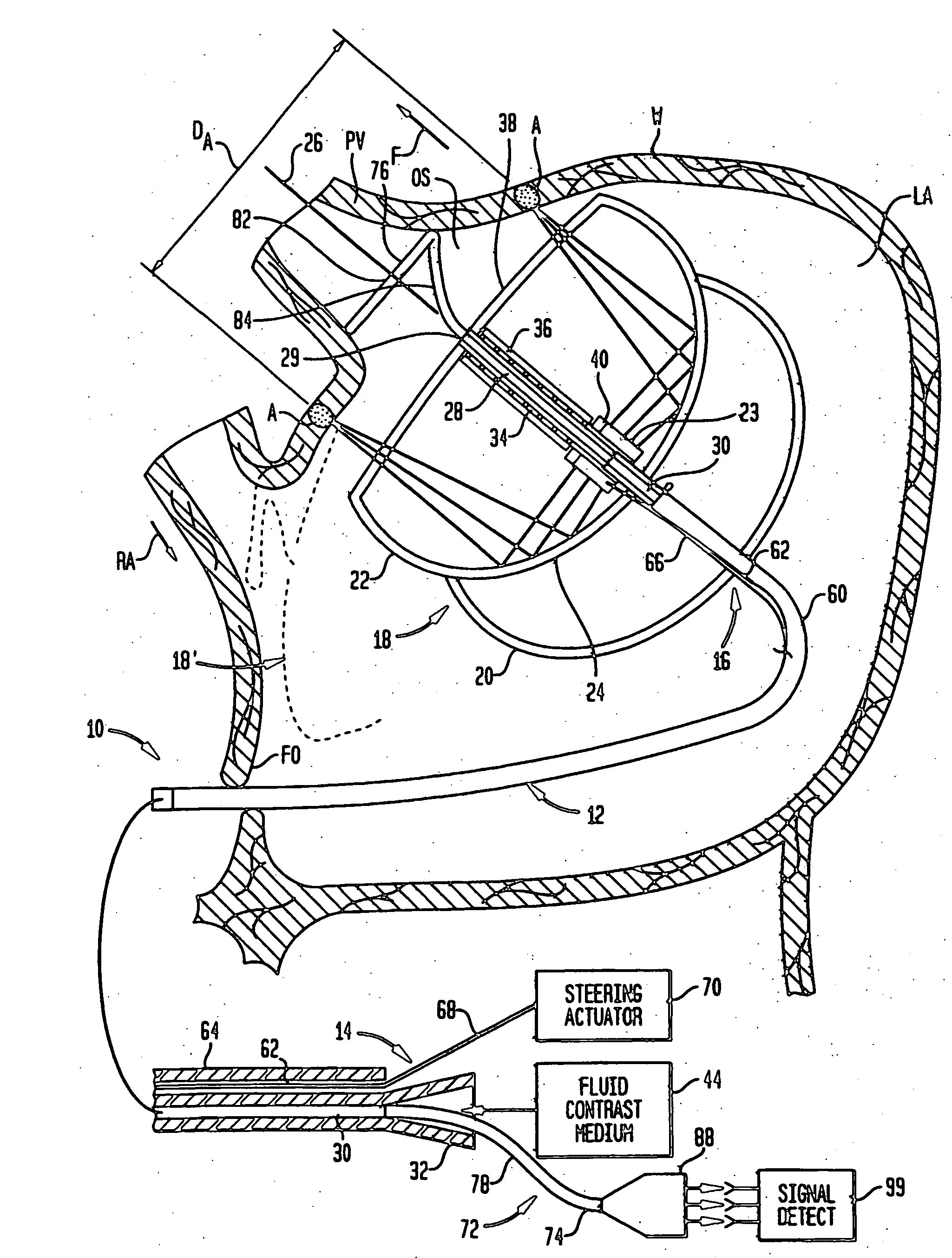
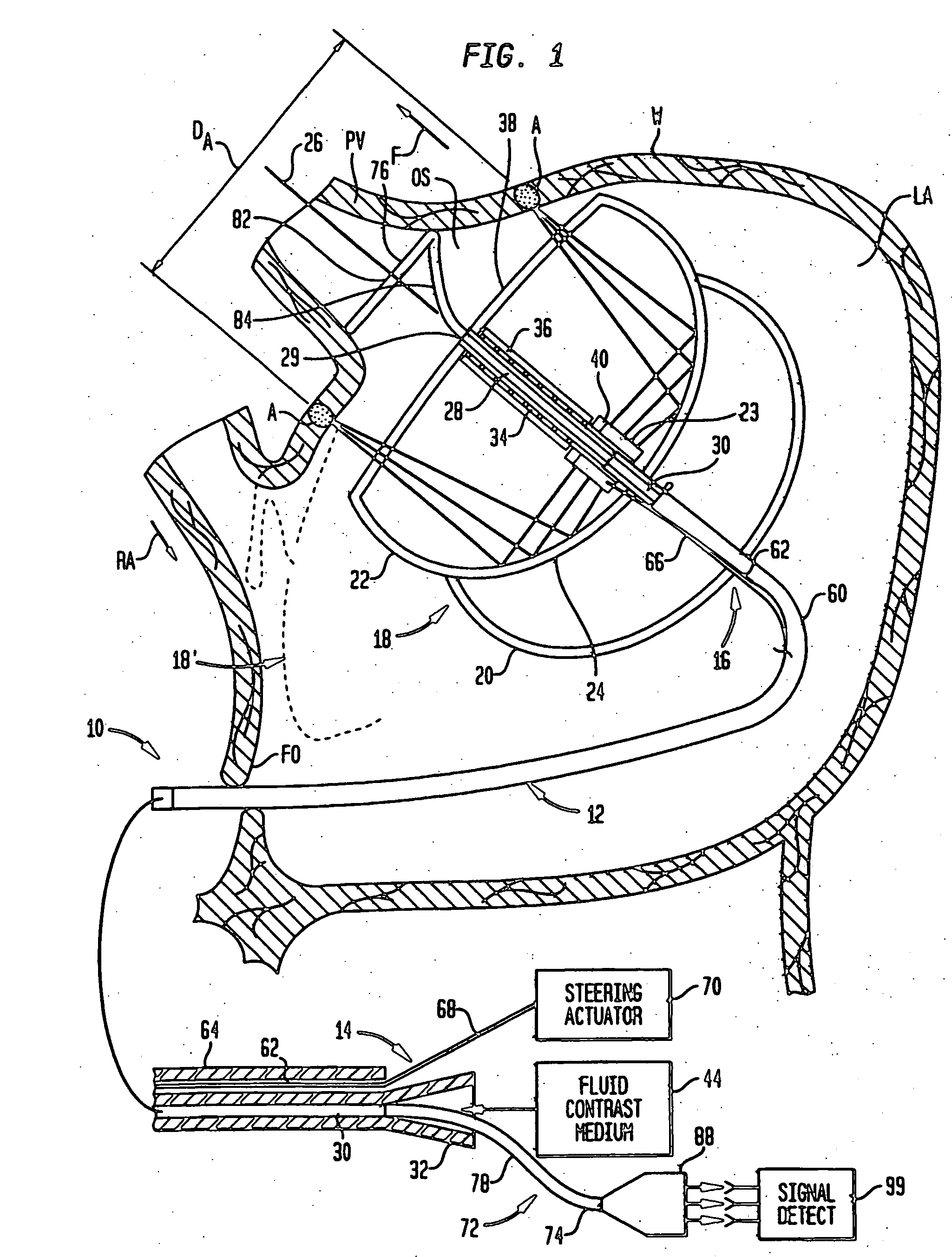
[0015]As further discussed below, apparatus according to this aspect of the invention allows the physician to position the expansible ablation structure as desired as, for example, to form a ring-like lesion. However, once the ablation device has been positioned, the sensor probe can be introduced readily through the passageway and is automatically aligned with the area to be ablated. For example, where the apparatus is used to form a ring-like lesion around a pulmonary vein or pulmonary vein ostium, the sensor probe will automatically be placed in alignment with the lesion and in alignment with the pulmonary vein and pulmonary vein ostium when it is introduced through the lumen and bore. Depending upon the radius of the hoop formed by the sensor, the hoop may be disposed inside the lesion to monitor electrical activity within the area enclosed or to be enclosed by the lesion. Alternatively, where the radius of the hoop formed by the sensing probe exceeds the radius of the ablation region, the hoop will lie outside of the ablation region, and will monitor electrical activity in this region.
[0016]The removable sensor probe does not impede other procedures such as introduction of a contrast medium through the passageway during positioning. The sensor probe can be placed at any time during the procedure to monitor electrical activity before or after ablation, or even during ablation. Because the catheter and ablation device serve as an introducer structure for the sensor probe, the sensor probe can be introduced readily, without interrupting the procedure. Moreover, because the sensor probe is removable, the apparatus may include more than one sensor probe, which may have different configurations and different sizes, so that the sensing electrodes can be placed at different locations.

Problems solved by technology

Providing electrical sensing structures on a balloon-like or other expansible ablation device complicates fabrication of the device and makes it more difficult to make the device collapse to a small diameter for advancing or withdrawing the device through the vascular system.
Further, mounting the electrodes on the same catheter as an ultrasonic transducer, as disclosed in the '484 patent, limits placement of the electrodes and the configuration of the transducer array and associated structures.
The particular structures shown in the '484 patent, for example, are not well suited to formation of a ring-like lesion or sensing of electrical potentials at numerous locations.
Use of a loop-forming sensing element entirely divorced from an ablation device, as contemplated in U.S. Pat. No. 6,628,976, necessarily requires separate steps for placement of such a device which adds both complexity and risk to the procedure.

Method used


Image

  • Ablation Devices with Sensor Structures
  • Ablation Devices with Sensor Structures
  • Ablation Devices with Sensor Structures

Examples


Embodiment Construction

[0032]As seen in FIG. 1, apparatus according to one embodiment of the invention includes an insertable structure 10 incorporating an elongated catheter 12 having a proximal end 14, which remains outside of the body, and a distal end 16 adapted for insertion into the body of the subject. As used in this disclosure with reference to structures which are advanced into the body of a subject, the “distal” end of such a structure should be taken as the end which is inserted first into the body and which penetrates to the greatest depth within the body, whereas the proximal end is the end of the structure opposite to the distal end. The insertable structure 10 also includes an ablation unit 18 mounted to the catheter adjacent distal end 16. Ablation unit 18 incorporates a reflector balloon 20 and a structural balloon 22 having a common wall 24. Reflector balloon 20 is linked to an inflation lumen (not shown) in catheter 10, which extends to the proximal end of the catheter and which is con...


PUM


Abstract

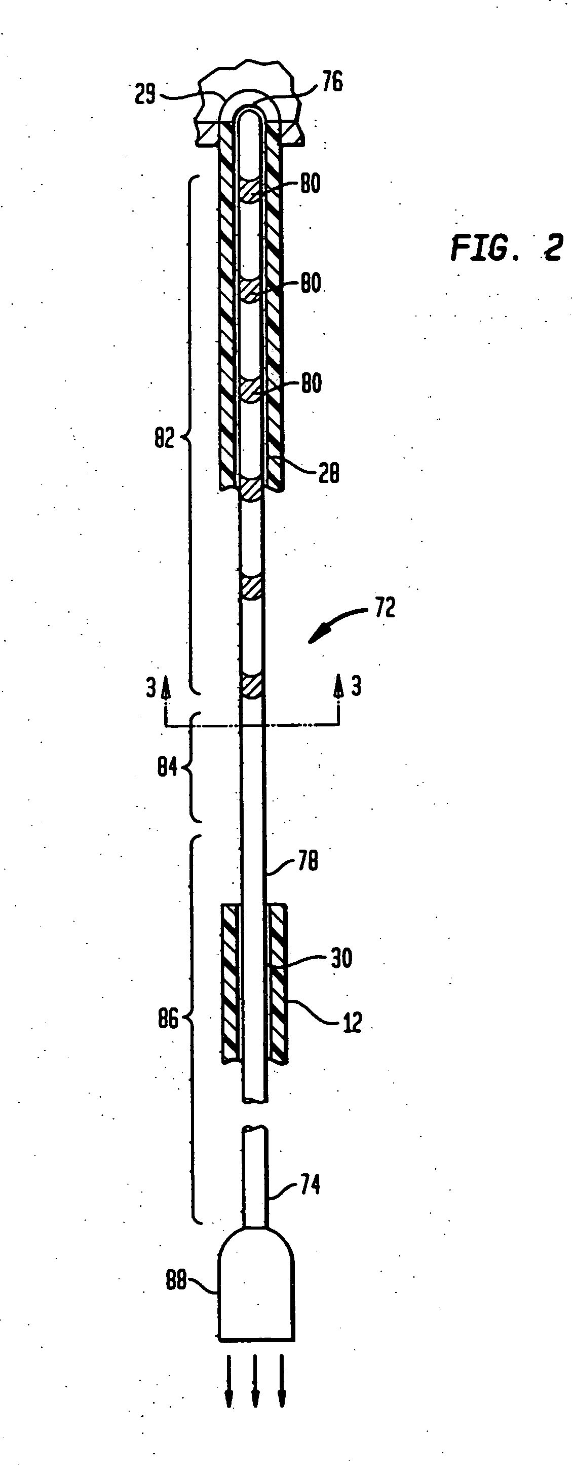
A cardiac ablation device, including a steerable catheter (10) and an expandable ablation element (18) incorporating one or more balloons (20, 22) at the distal end of the catheter, has a continuous passageway (28, 30) extending through it from the proximal end of the catheter to the distal side of the expandable ablation element. A probe (72) carrying electrodes is introduced through this passageway and deploys, under the influence of its own resilience, to a structure incorporating a loop (82) which is automatically aligned with the axis of the expandable ablation device, so that minimal manipulation is required to place the sensor probe.

Description

CROSS-REFERENCE TO RELATED APPLICATIONS[0001]The present application claims the benefit of the filing date of U.S. Provisional Patent Application No. 60 / 563,581, filed Apr. 19, 2004, the disclosure of which is hereby incorporated herein by reference.BACKGROUND ART[0002]The present invention relates to apparatus and methods for cardiac ablation and to sensor structures useful in such apparatus and methods.[0003]Contraction or “beating” of the heart is controlled by electrical impulses generated at nodes within the heart and transmitted along conductive pathways extending within the wall of the heart. Certain diseases of the heart known as cardiac arrhythmias involve abnormal generation or conduction of the electrical impulses. One such arrhythmia is atrial fibrillation or “AF.” Certain cardiac arrhythmias can be treated by deliberately damaging the tissue along a path crossing a route of abnormal conduction, either by surgically cutting the tissue or by applying energy or chemicals t...

Claims


Application Information

Patent Timeline
Patent Type & Authority Applications(United States)
IPC IPC(8): A61B18/04A61N7/02A61B5/296A61B17/00A61B17/22A61B18/18
CPCA61B2017/00053A61B2017/22024A61B17/2202A61N7/022A61B2017/22062A61B18/18A61B18/12A61B18/00
Inventor WARNKING, REINHARDJUNG, EUGENENAKAGAWA, HIROSHIPACHECO, ROBERT C.
Owner BOSTON SCI SCIMED INC
Why Eureka
Try Eureka