Gui With Trend Analysis for an Implantable Restriction Device and a Data Logger

a technology of restricting device and trend analysis, which is applied in the field of communication system, can solve the problems of high risk of severe health problems, difficult to determine how the adjustment is proceeding, and high cost of fluoroscopy, and achieve the effects of raising concerns about radiation dosage and high cos

Inactive Publication Date: 2008-10-09
ETHICON ENDO SURGERY INC
View PDF117 Cites 122 Cited by
  • Summary
  • Abstract
  • Description
  • Claims
  • Application Information

AI Technical Summary

Benefits of technology

[0008]In one aspect, a display for a physiological monitoring device displaying information from or related to an implantable restriction device is provided. For example, an exemplary display can include a simulated graphic of a disposition of a region enclosed by an implantable restriction device, such as an adjustable gastric band, the simulated graphic indicating a size of the disposition through the region. The indicated size can be based at least in part on a parameter sensed by the implantable restriction device and communicated to the physiological monitoring device. Sensed parameters, in this and other embodiments described herein, can include a wide variety of parameters such as pressure, pulse count, pulse width, pulse duration, pulse amplitude, pulse frequency, sensed electrical characteristics, and so on. In some embodiments, the simulated graphic can include one or more isobars displayed on the graphic representation of the enclosed region, the isobars representing sensed parameter values so that a perimeter of the disposition in the region is indicative of the sensed parameter. The isobars can change color to signal a condition related to the sensed parameter values. In other embodiments, the simulated graphic can include an image of a cross-section of a stoma, an image of the restriction device disposed around an anatomical lumen, an image of a bolus, icons, markings, and / or three dimensional images. The simulated graphic also can include a video image for showing a change in the size of the opening in accordance with pressure (or other parameter) sensed by the implantable restriction device over a time period. The simulated graphic also can be based on an image obtained from the body of a patient in which the implantable restriction device is implanted. The display can further include a textual indicator of a sensed parameter, sensed parameter data shown on a graph or dial indicator, and / or an indication of a restriction state of the implantable restriction device.

Problems solved by technology

Morbid obesity, in which a person is 100 pounds or more over ideal body weight, in particular poses significant risks for severe health problems.
During these gastric band adjustments, it has been difficult to determine how the adjustment is proceeding, and whether the adjustment will have the intended effect.
In an attempt to determine the efficacy of an adjustment, some physicians have utilized fluoroscopy with a Barium swallow as the adjustment is being performed, although fluoroscopy can be both expensive and raise concerns about radiation dosage.
This method, however, only assures that the patient is not obstructed, and does not provide any information about the efficacy of the adjustment.
Oftentimes, a physician may simply adopt a “try as you go” method based upon their prior experience, and the results of an adjustment may not be discovered until hours or days later, when the patient experiences a complete obstruction of the stomach cavity, or the band induces erosion of the stomach tissue due to excessive pressure on the tissue walls.
In addition, tracking or monitoring the long-term performance of the gastric band and / or the patient has been difficult in the past, but promises a wide range of benefits.

Method used


Image

  • Gui With Trend Analysis for an Implantable Restriction Device and a Data Logger
  • Gui With Trend Analysis for an Implantable Restriction Device and a Data Logger
  • Gui With Trend Analysis for an Implantable Restriction Device and a Data Logger

Examples


Embodiment Construction

[0104]The following description of certain examples of the invention should not be used to limit the scope of the present invention. Other examples, features, aspects, embodiments, and advantages of the invention will become apparent to those skilled in the art from the following description, which is by way of illustration, one of the best modes contemplated for carrying out the invention. As will be realized, the invention is capable of other different and obvious aspects, all without departing from the invention. Accordingly, the drawings and descriptions should be regarded as illustrative in nature and not restrictive. The features illustrated or described in connection with one exemplary embodiment may be combined with the features of other embodiments. Such modifications and variations are intended to be included within the scope of the present invention.

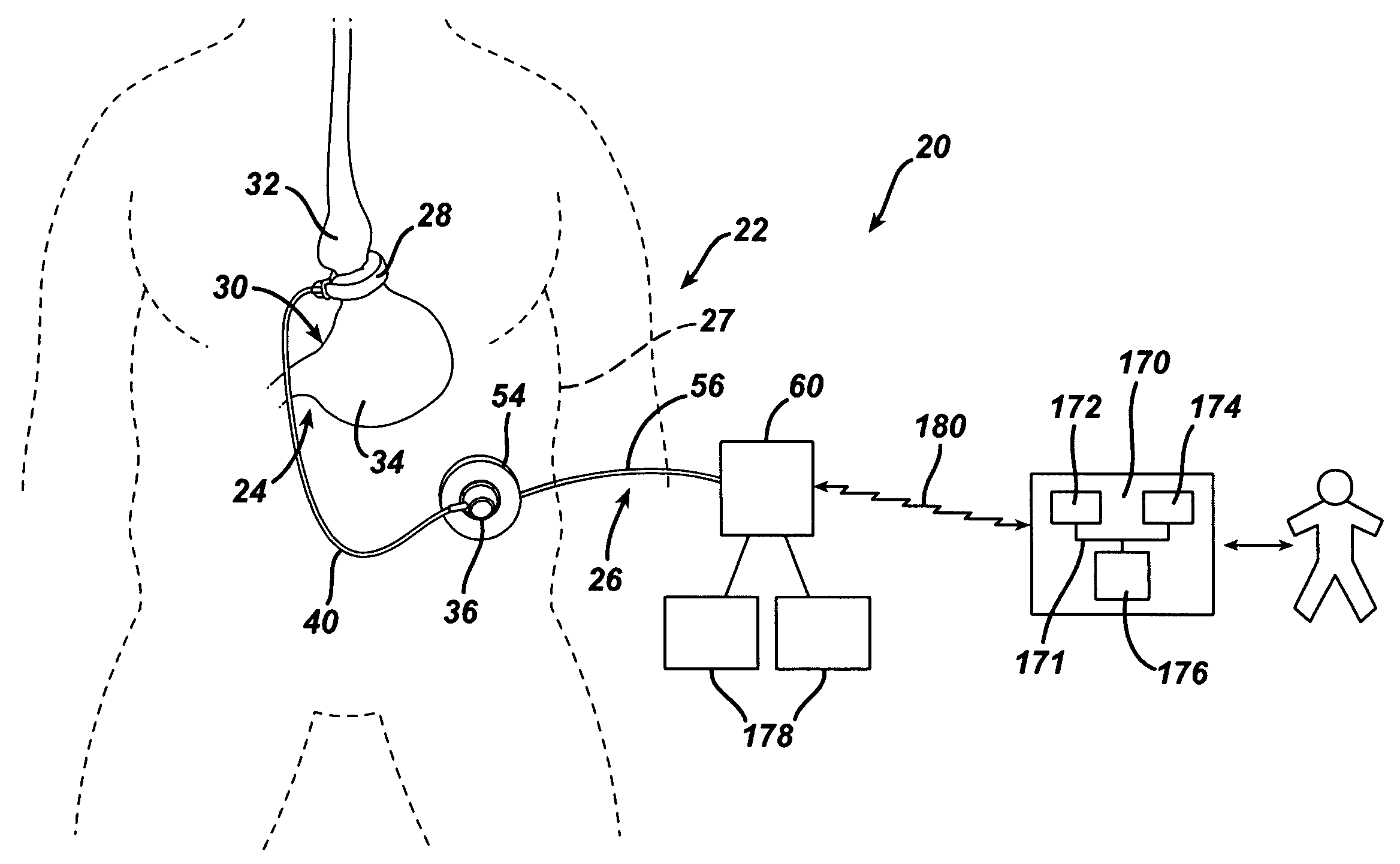
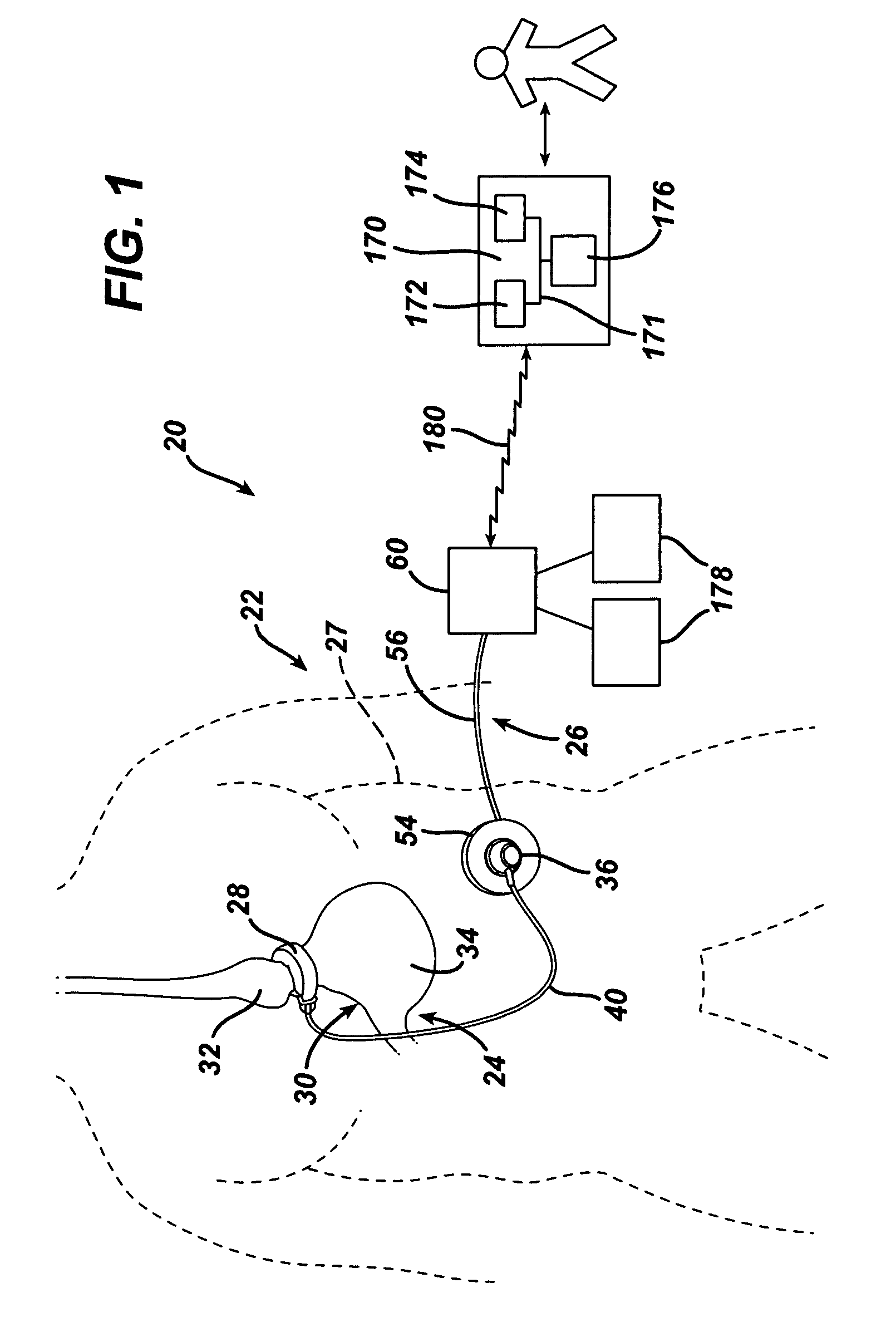
[0105]Referring now to the drawings in detail, wherein like numerals indicate the same elements throughout the views, FIG. 1...


PUM


Abstract

An implantable restriction device can be configured to provide a restriction in a patient, for example as a function of the pressure of fluid. The implantable restriction device can include one or more sensors configured to sense a variety of parameters, such as pressure of the fluid within the implantable restriction device, pulse width, pulse amplitude, pulse count, pulse duration, or frequency, electrical characteristics, or other parameters. Data obtained by the one or more sensors (for example, the data representing pressure, pulse characteristics, and so on) may be communicated to a device located external to the patient, such as a data logger, using telemetry coils or other communicators. The data logger may store the data, and may communicate the data to a remote location via a network such as the Internet. A docking station may be provided to couple the data logger to a network and/or to recharge a cell in the data logger. The logged data may be analyzed and/or displayed using a variety of techniques to assess and/or track the condition of the restriction device or of the patient, to monitor patient physiology, or for other purposes.

Description

FIELD OF THE INVENTION[0001]Embodiments of the present invention relate generally to an implanted restrictive opening device and, more particularly, to a communication system for monitoring physiological parameters related to an implanted food intake restriction device.BACKGROUND OF THE INVENTION[0002]Obesity is a growing concern, particularly in the United States, as the number of obese people continues to increase, and more is learned about the negative health effects of obesity. Morbid obesity, in which a person is 100 pounds or more over ideal body weight, in particular poses significant risks for severe health problems. Accordingly, a great deal of attention is being focused on treating obese patients. One method of treating morbid obesity has been to place a restriction device, such as an elongated band, about the upper portion of the stomach. Gastric bands have typically comprised a fluid-filled elastomeric balloon with fixed endpoints that encircles the stomach just inferior...

Claims


Application Information

Patent Timeline
Patent Type & Authority Applications(United States)
IPC IPC(8): G06F3/048
CPCA61B5/02055A61B5/0022A61B5/024A61B5/03A61B5/0402A61B5/076A61B5/1116A61B5/1118A61B5/14532A61B5/4205A61B17/12009A61B17/1355A61B2017/00557A61B2019/464A61B2560/0219A61B2560/0252A61B2560/0257A61B2560/0261A61B2560/045A61F5/0003A61F5/0056A61F2250/0002A61M39/0208G06F3/0481A61B5/002A61B5/021A61B2090/064G16H40/67A61B5/318
Inventor DLUGOS, DANIEL F.BROCKMEIER, PETERBERGER, MATTHEW A.BYRUM, RANDAL T.DOLL, KEVIN R.GAYOSO, GASPAR M.JENSEN, DUSTIN R.KRUMANAKER, DAVID T.MARCOTTE, AMY L.ORTIZ, MARK S.PLESCIA, DAVID N.YATES, DAVID C.
Owner ETHICON ENDO SURGERY INC
Why Eureka
Try Eureka