Particulate Trap with Coated Fiber Layer and Exhaust System Having the Particulate Trap

a technology of coating fiber and particulate trap, which is applied in the direction of filtration separation, coating, combination devices, etc., can solve the problems of achieving synergistic effects and achieve the effect of facilitating mixing

Inactive Publication Date: 2008-10-16
EMITEC GESELLSCHAFT FUR EMISSIONSTECHNOLOGIE MBH
View PDF9 Cites 37 Cited by
  • Summary
  • Abstract
  • Description
  • Claims
  • Application Information

AI Technical Summary

Benefits of technology

[0015]It is accordingly an object of the invention to provide a particulate trap with a coated fiber layer and an exhaust system having the particulate trap, which overcome the hereinafore-mentioned disadvantages of the heretofore-known devices of this general type, which have improved effectiveness with regard to conversion of pollutants contained in exhaust gas, which provide the possibility of providing exhaust-gas systems having a particularly small structure in particular for automobiles with a diesel engine and in which production, assembly and maintenance of such exhaust-gas systems is significantly simplified and thereby made less expensive.

Problems solved by technology

Moreover, surprisingly, synergistic effects are also achieved.

Method used


Image

  • Particulate Trap with Coated Fiber Layer and Exhaust System Having the Particulate Trap
  • Particulate Trap with Coated Fiber Layer and Exhaust System Having the Particulate Trap
  • Particulate Trap with Coated Fiber Layer and Exhaust System Having the Particulate Trap

Examples


Embodiment Construction

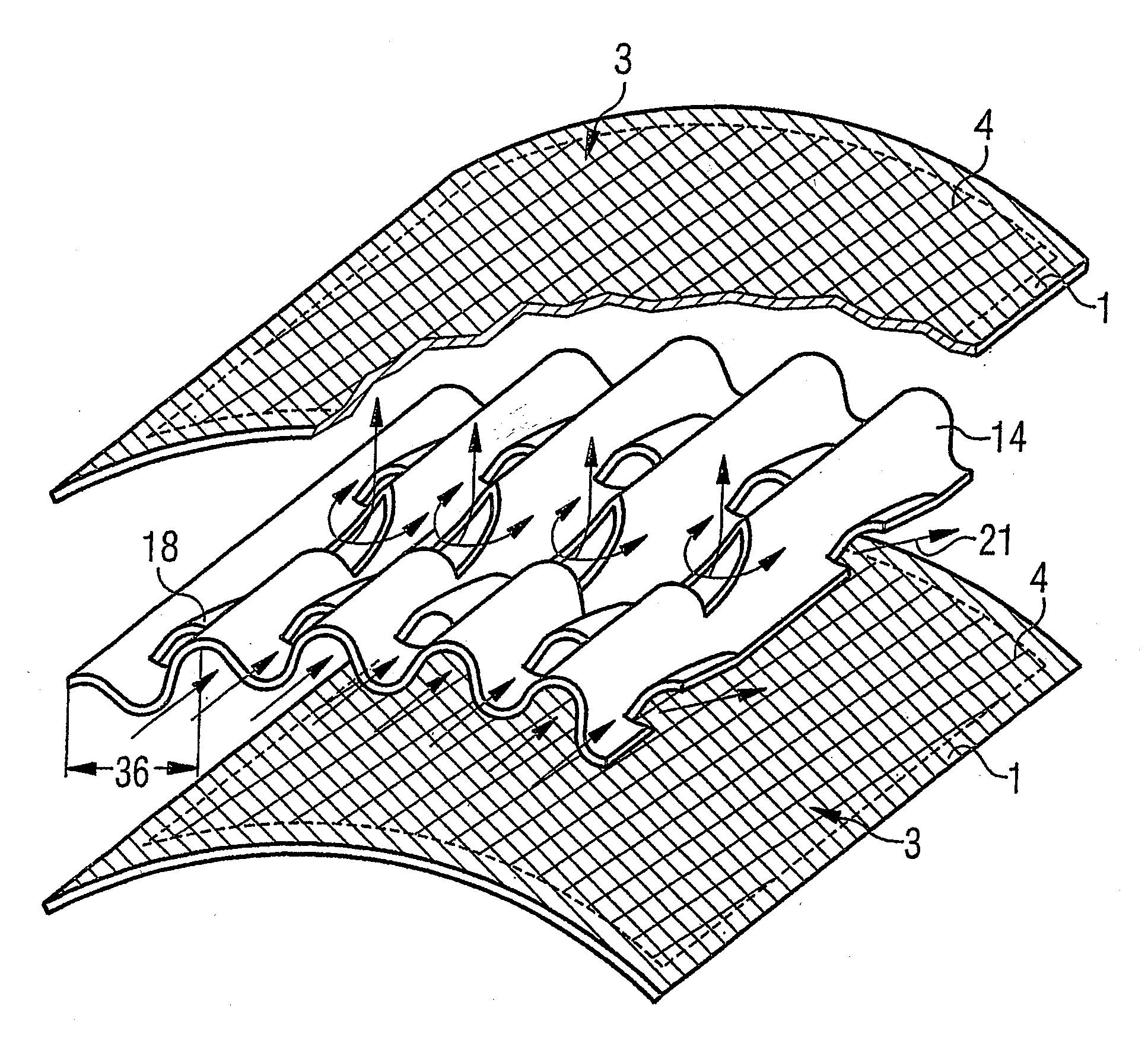
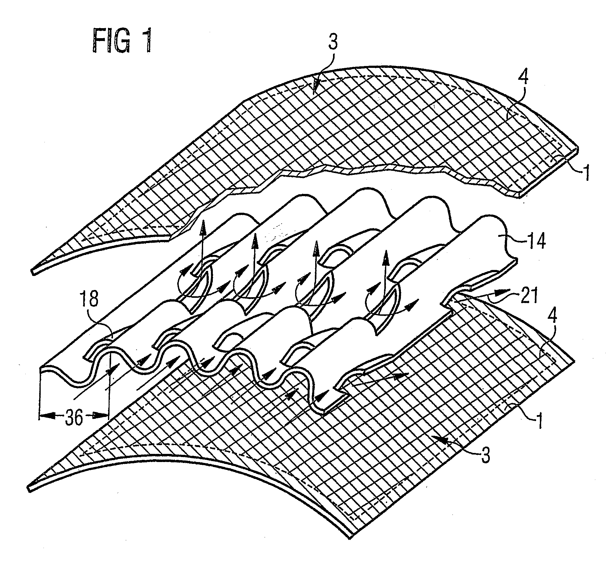
[0060]Referring now to the figures of the drawings in detail and first, particularly, to FIG. 1 thereof, there is seen a fragmentary, diagrammatic, exploded view of a particulate trap as is used, for example, to treat exhaust gas from mobile internal combustion engines. The figure illustrates two fiber layers 1 according to the invention, between which a metal foil 14 is disposed. The fiber layers 1 each have a section 3 in which a coating 4 is disposed. This coating 4 may be the coating of an oxidation catalyst, of a three-way catalyst and / or of an SCR catalyst. It is preferable for the metal foils 14 (at least in partial regions) to have a catalytically active and / or storing coating. It is usual for the adjacent layers to bear against one another, and they are preferably connected to one another by a joining technique, in particular by brazing. For this purpose it is necessary, for example, for a partial region, in particular an edge of the fiber layer 1, not to be coated, in orde...


PUM

PropertyMeasurementUnit
mean diameteraaaaaaaaaa
porosityaaaaaaaaaa
porosityaaaaaaaaaa

Abstract

An open particulate trap for purifying exhaust gases from mobile internal combustion engines includes at least one at least partially structured metal foil and at least one high-temperature-resistant fiber layer having metal fibers defining the open particulate trap for purifying exhaust gases from mobile internal combustion engines. The fiber layer has a section and, at least in the section, a catalytically active coating being an SCR catalyst. An exhaust system of an automobile internal combustion engine includes an exhaust pipe defining a flow direction and at least the following components disposed in succession in the flow direction: a reducing-agent feed for supplying liquid urea and the particulate trap.

Description

CROSS-REFERENCE TO RELATED APPLICATIONS[0001]This is a divisional application of application Ser. No. 11 / 146,369, filed Jun. 6, 2005, which is a continuing application, under 35 U.S.C. §120, of International Application No. PCT / EP2003 / 012455, filed Nov. 7, 2003; this application also claims the priority, under 35 U.S.C. §119, of German Patent Application No. 10 257 113.9, filed Dec. 5, 2002; the prior applications are herewith incorporated by reference in their entirety.BACKGROUND OF THE INVENTION[0002]Field of the Invention[0003]The invention relates to a particulate trap with a coated high-temperature-resistant fiber layer for purifying exhaust gases from automobile internal combustion engines. The invention also relates to an exhaust system of an automobile internal combustion engine having the particulate trap.[0004]If one considers the purification of exhaust gases, in particular from diesel engines, it is known that hydrocarbons (HC) and carbon monoxides (CO) in exhaust gas ca...

Claims


Application Information

Patent Timeline
Patent Type & Authority Applications(United States)
IPC IPC(8): F01N3/10B01D39/20B01D53/88B01D53/94B01J35/04B01J35/06B01J37/02F01N3/022F01N3/035
CPCB01D39/2044B01D53/885B01D53/9454B01D2239/0478B01D2239/0695B01D2239/1208B01D2239/1216B01D2239/1233B01J35/04B01J35/06B01J37/0215F01N3/0226F01N3/035Y02T10/22Y02T10/24Y02A50/20Y02T10/12B01D53/94F01N3/022
Inventor BRUCK, ROLF
Owner EMITEC GESELLSCHAFT FUR EMISSIONSTECHNOLOGIE MBH
Why Eureka
Try Eureka