Thermoelectric energy conversion

a technology of energy conversion and thermoelectric generator, applied in the manufacture/treatment of thermoelectric devices, thermoelectric devices, lighting and heating apparatus, etc., can solve the problems of inefficiency of production cost, power requirements that may not justify conventional generation methods, and solar cells are responsive to a limited portion

Inactive Publication Date: 2008-10-16
WAFERMASTERS
View PDF2 Cites 15 Cited by
  • Summary
  • Abstract
  • Description
  • Claims
  • Application Information

AI Technical Summary

Benefits of technology

[0012]In a fifth embodiment, the circulating fluids may be provided by external sources to maintain a temperature difference between opposing sides of the thermoelectric pile, thereby causing the thermoelectric generator to produce electrical power with or without radiation energy incident on the heat absorbing body.

Problems solved by technology

Discarded heat energy is a cost of production that contributes to production cost inefficiency and may be measured as a direct cost of energy.
Solar cells are a conventional source of electrical power in numerous applications, particularly where the cost of energy delivery or power requirement does not justify the investment in infrastructure.
An example is a source of electrical power derived from sunlight in an at-sea application, where standard power generation is not available and power requirements may not justify conventional generation methods (i.e., oil or coal fired power generators).
However, solar cells are responsive to a limited portion of the visible and near- infrared spectrum, whereas the solar spectrum reaching the surface of the earth is considerably broader.

Method used


Image

  • Thermoelectric energy conversion
  • Thermoelectric energy conversion
  • Thermoelectric energy conversion

Examples


Embodiment Construction

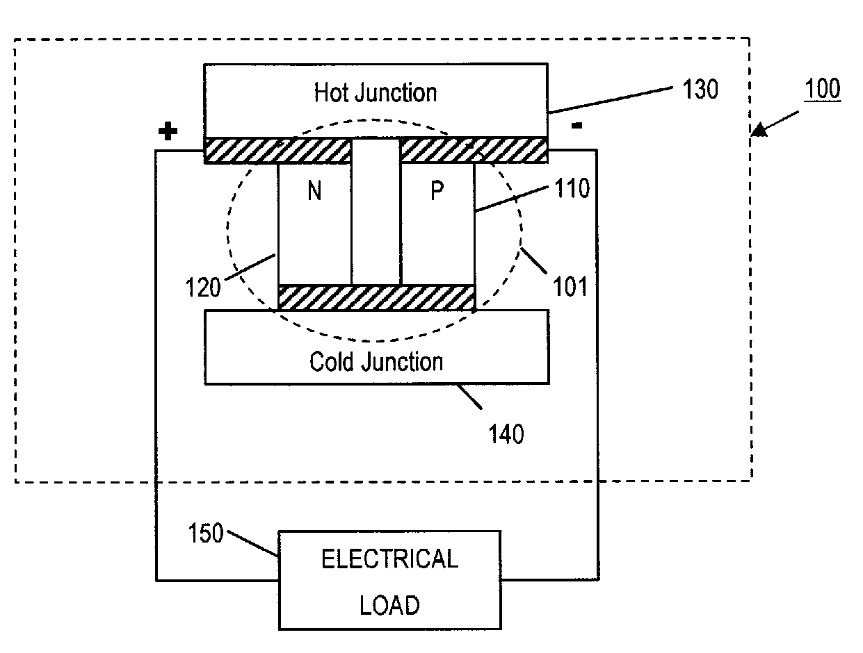
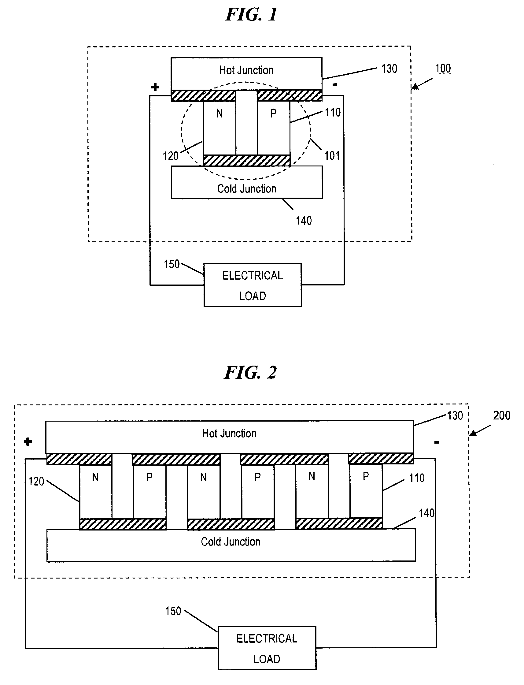
[0024]The concept of thermoelectric generation is well known. FIG. 1 illustrates a typical Seebeck Effect thermoelectric couple. A thermoelectric device 100 for electrical power generation usually involves using conventional thermoelectric couples 101, i.e., pairs of P and N doped semiconductor “pellets”110 and 120, respectively, of materials such as, for example, bismuth / telluride.

[0025]The performance of thermoelectric couple 101 is based on well known thermoelectric generation principles, commonly known as the Seebeck effect, which involves producing a current in a closed circuit of two dissimilar materials, i.e., N doped pellets 110 and P doped pellets 120, forming two junctions, where one junction is held at a higher temperature (hot junction 130) than the other junction (cold junction 140).

[0026]The elevated temperature at hot junction 130 drives electrons in N doped pellet 120 toward cold junction 140 and drives “holes” in P doped pellet 110 in the same direction, i.e., towar...


PUM


Abstract

A thermoelectric power generator includes a thermoelectric pile in a chamber. A window admits light and / or heat radiation such as solar radiation into the chamber, which is absorbed in a radiation absorbing body in thermal contact with a first side of the thermoelectric pile, whereby the temperature of the first side is raised. A second side of the thermoelectric pile is in thermal contact with the wall of the chamber, which is a heat sink to maintain the second side at a lower temperature. The temperature difference produces a voltage difference at electrical contacts to the thermoelectric pile, which is capable of powering electrical devices.

Description

BACKGROUND[0001]1. Field of Invention[0002]This invention generally relates to energy conversion systems and methods and, more particularly, to a solar powered thermoelectric generator.[0003]2. Related Art[0004]In many industrial processes a considerable quantity of heat energy is generated that is discarded as an unused byproduct. Conventional methods for removing or eliminating this heat may be through evaporation or heat exchange, eventually to the environment. Discarded heat energy is a cost of production that contributes to production cost inefficiency and may be measured as a direct cost of energy. It would be desirable to recapture and use such wasted energy.[0005]Solar cells are a conventional source of electrical power in numerous applications, particularly where the cost of energy delivery or power requirement does not justify the investment in infrastructure. An example is a source of electrical power derived from sunlight in an at-sea application, where standard power ge...

Claims


Application Information

Patent Timeline
Patent Type & Authority Applications(United States)
IPC IPC(8): H01L31/024
CPCH01L35/30Y02E10/40F24S20/00H10N10/13
Inventor YOO, WOO SIK
Owner WAFERMASTERS
Why Eureka
Try Eureka