

Carbonization of metal caps
- Summary
- Abstract
- Description
- Claims
- Application Information
AI Technical Summary
Benefits of technology
Problems solved by technology
Method used
Image

Examples
Embodiment Construction
[0018]The making and using of the presently preferred embodiments are discussed in detail below. It should be appreciated, however, that the present invention provides many applicable inventive concepts that can be embodied in a wide variety of specific contexts. The specific embodiments discussed are merely illustrative of specific ways to make and use the invention, and do not limit the scope of the invention.
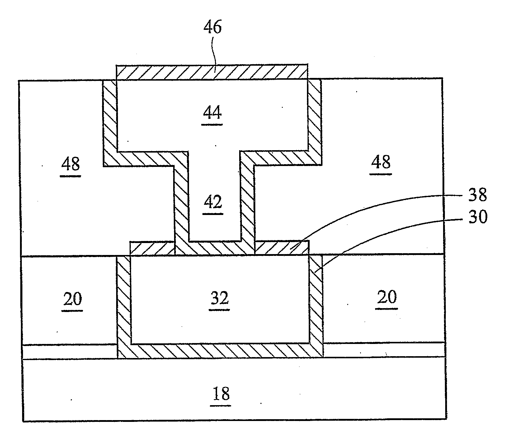
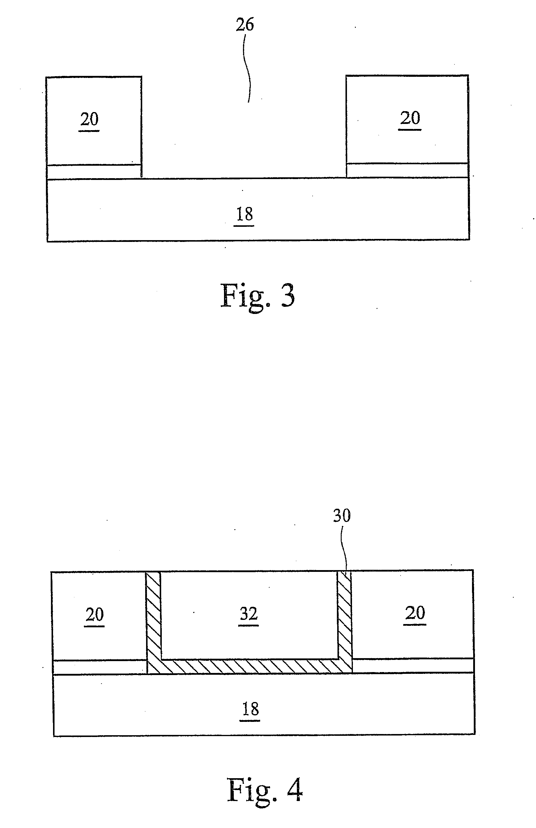
[0019]Interconnect structures comprising metal carbide layers and methods of forming the same are provided. The intermediate stages of manufacturing preferred embodiments of the present invention are illustrated in FIGS. 3 through 8B. Variations are then discussed. Throughout various views and illustrative embodiments of the present invention, like reference numbers are used to designate like elements.
[0020]FIG. 3 illustrates the formation of opening 26 in dielectric layer 20, which is formed over a schematically illustrated base structure 18. Base structure 18 may include a ...
PUM
 Abstract
Description
Claims
Application Information