
Advanced automobile accident detection data recordation system and reporting system

a data recorder and automobile technology, applied in the field of advanced automobile accident detection data recorder and reporting system, can solve the problems of inability to incorporate advanced wireless communication technology for transmitting accident data in real-time or near-real-time, many known vehicle accident detection systems are limited in their ability to capture or process accurate, and prior art systems may be complex and costly to implement. , to achieve the effect of increasing capacity, increasing revenue opportunities, and increasing economic benefits

Inactive Publication Date: 2008-10-16
LAGASSEY PAUL J
View PDF7 Cites 131 Cited by
  • Summary
  • Abstract
  • Description
  • Claims
  • Application Information

AI Technical Summary

Benefits of technology

[0046]Accordingly, what is needed in the art is a vehicle accident detection and data recordation and transmission system that provides a cost effective manner of placing one or more video cameras, microphones and data collection and transmission apparatus in proximity to traffic intersections, or other desired locations, in order to detect and temporarily store accident-related images and sounds, together with other accident-related data such as time and location, and to transmit said data to a remote location where the information can be reviewed immediately for the purpose of screening false alarms, assessing the severity of the accident and dispatching an appropriate level of emergency response, and where the transmitted data can be permanently stored to create a record of the accident that can be distributed to the authorities, insurance companies and the parties themselves, and be used in subsequent legal proceedings. To this end, one aspect of the present invention provides a business model for financing at least a portion of the system by imposing a usage fee for to access to authenticated data usable as evidence. The availability of a system for recording and maintaining data in a reliable manner for use as evidence may also reduce the burden on the Courts, since adjudication will be based on a richer and less subjective form of evidence, and may incentivize and promote out-of-court settlements.
[0109]The communication link may comprise a wireless transceiver, which generally simplifies installation. Alternately, the communications physical transport layer can include coaxial cable, twisted pair, cellular communications, point-to-point radio frequency wireless, point-to-point microwave wireless, line-of-sight optical, fiber optic, and ad hoc radio frequency network. According to one embodiment, the communication link comprises a primary link and a backup link, using a different physical transport layer, the selective communication preferentially occurring through the primary link, and in an event of failure of the selective communication through the primary link, then through the backup link. The backup link, in this case, may employ a more expensive communications method. This, in turn, allows selection of a less expensive physical transport layer for the primary link, even if the reliability of this is less than required.

Problems solved by technology

Many of the known vehicle accident detection systems are limited in their ability to capture or process accurate data or to accurately and timely send the processed data to the proper location to enable authorities to properly assess accident damage and liability.
Further, these systems generally do not incorporate advanced wireless communication technology for transmitting the accident data in real-time or near real-time, and satellite navigation technology for providing accurate timing and location information.
Furthermore, prior art systems may be complex and costly to implement and are therefore may be relatively impractical and infeasible for wide deployment.

Method used


Image

  • Advanced automobile accident detection data recordation system and reporting system
  • Advanced automobile accident detection data recordation system and reporting system
  • Advanced automobile accident detection data recordation system and reporting system

Examples


Embodiment Construction

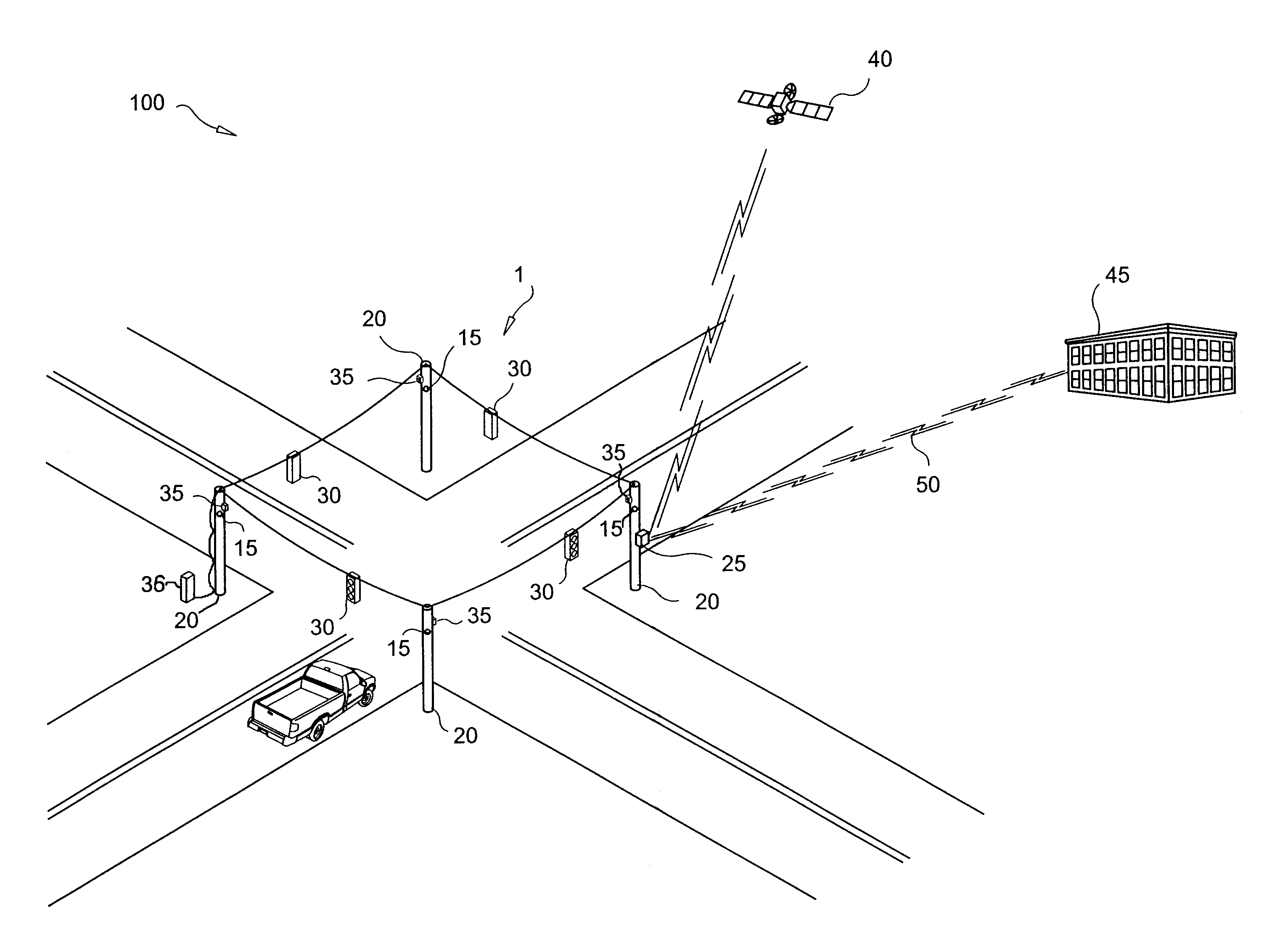
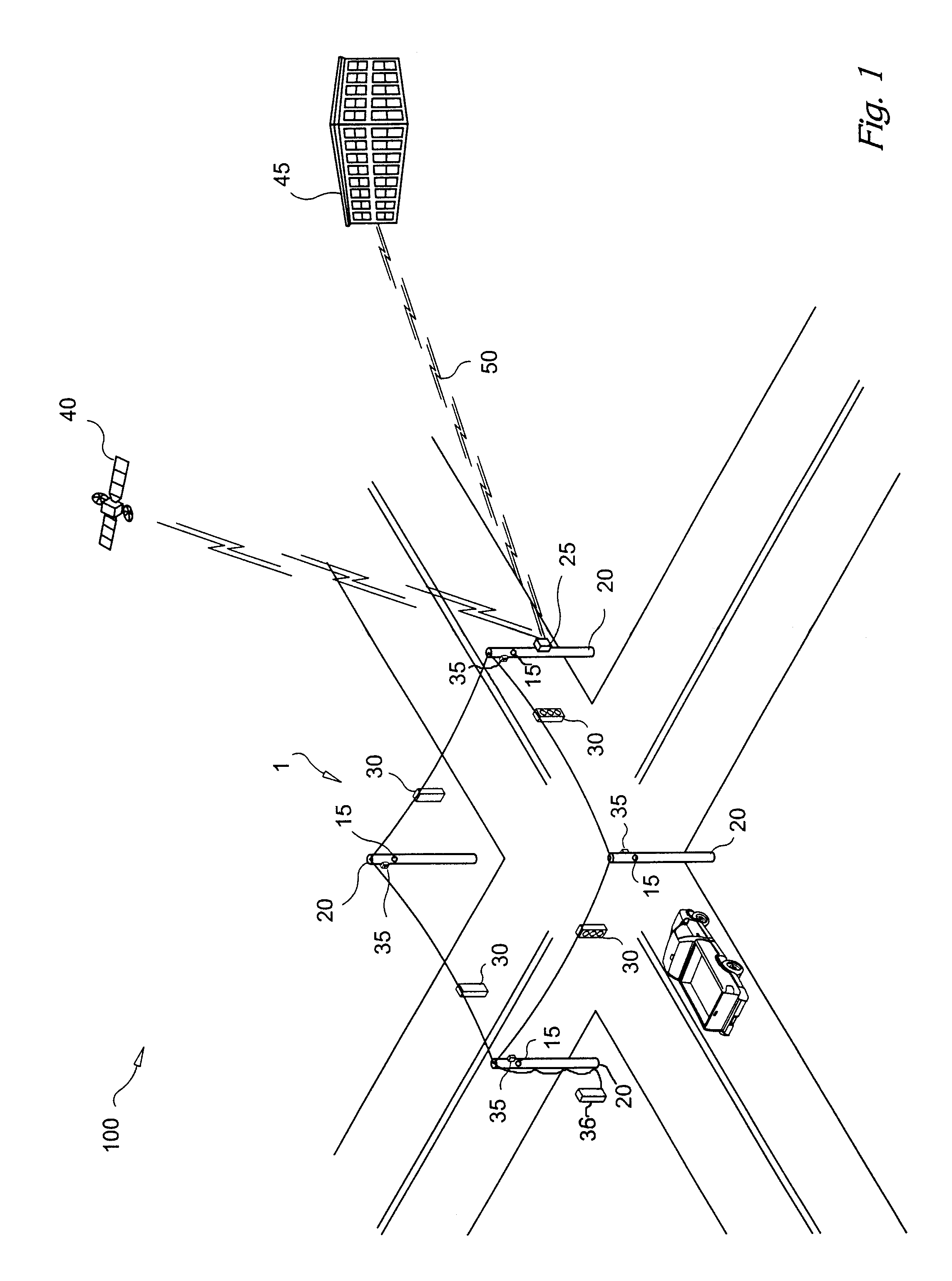
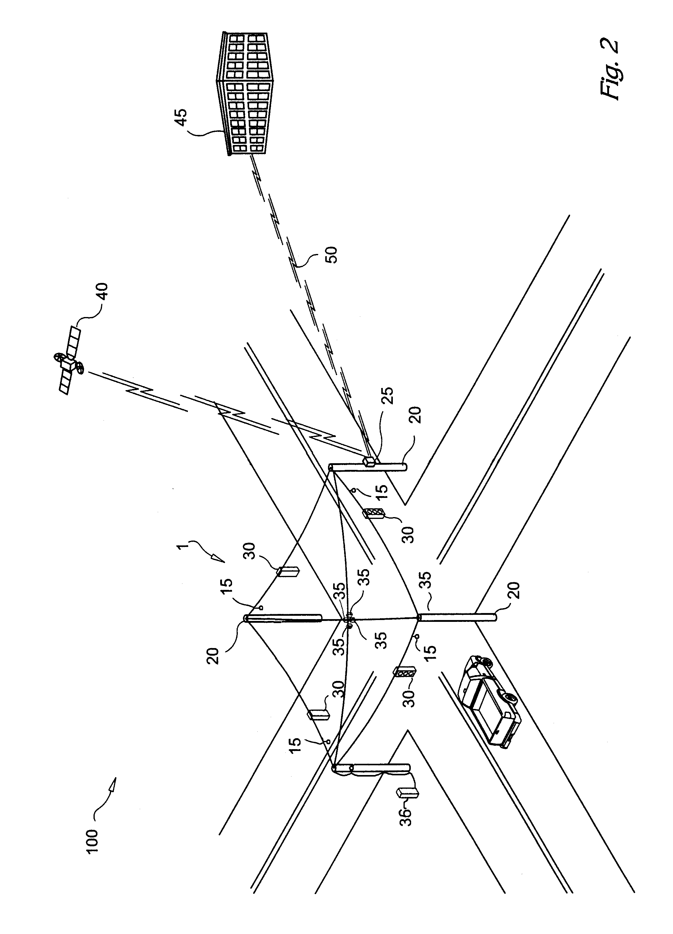
[0130]As seen in FIG. 1 the present invention is illustrated and generally designated as the system 100. The system 100 comprises one or more listening devices 15 placed proximate a traffic scene 1 which is referred to as the desired location. The desired location 1 can be any street, a section of highway, an intersection, or any other place where a traffic accident can occur. Listening devices 15, preferably microphones, are be mounted strategically at one or more positions proximate the desired location 1. In FIG. 1, the microphones 15 are place on utility poles 20, but they can be placed on any object proximate the desired location 1 such as underneath the traffic signals 30, suspended on wires above the intersection as shown in FIG. 2, or on other structures such as buildings so long as they are placed to allow accurate capture of the acoustic signals at the desired location 1.

[0131]The microphones 15 are connected to the control unit 25 either by wired or wireless means, and th...


PUM


Abstract

A system for monitoring a location to detect and report a vehicular incident, comprising a transducer for detecting acoustic waves at the location, and having an audio output; a processor for determining a probable occurrence or impending occurrence of a vehicular incident, based at least upon said audio output; an imaging system for capturing images of the location, and having an image output; a buffer, receiving said image output, and storing at least a portion of said images commencing at or before said determination; and a communication link, for selectively communicating said portion of said images stored in said buffer with a remote location and at least information identifying the location, wherein information stored in said buffer is preserved at least until an acknowledgement of receipt is received representing successful transmission through said communication link with the remote location.

Description

CROSS REFERENCE TO RELATED APPLICATION[0001]The present application claims benefit of priority from U.S. Provisional Patent Application 60 / 522,749 filed Nov. 3, 2004, which is expressly incorporated herein by reference. The present application is a continuation of U.S. patent application Ser. No. 11 / 267,732, filed Nov. 3, 2005, now U.S. Pat. No. 7,348,895, issued Mar. 25, 2008, which is expressly incorporated herein by reference.BACKGROUND OF THE INVENTION[0002]The invention generally relates to an automobile accident detection and data recordation and reporting system, and in particular to a system which detects accidents based on a set of characteristic sounds or other cues.[0003]Traffic accidents cause significant costs in terms of direct loss, consequential loss, and societal loss due to obstruction of the roadway in the aftermath of an accident. Another issue is the allocation of direct costs, for example when more than one vehicle is involved, the vehicle at fault is generally...

Claims


Application Information

Patent Timeline
Patent Type & Authority Applications(United States)
IPC IPC(8): G08G1/09
CPCG07C5/008G07C5/0891G08G1/205G08G1/0116
Inventor LAGASSEY, PAUL J.
Owner LAGASSEY PAUL J
Learn More