Method and apparatus for antenna systems

a technology of antenna system and antenna body, applied in the field of antenna system, can solve the problems of high cost, space-consuming, heavy, etc., and achieve the effect of reducing the cost of the subsystem, and reducing the cost of the system

Active Publication Date: 2008-10-16
THE BOEING CO
View PDF6 Cites 1 Cited by
  • Summary
  • Abstract
  • Description
  • Claims
  • Application Information

AI Technical Summary

Benefits of technology

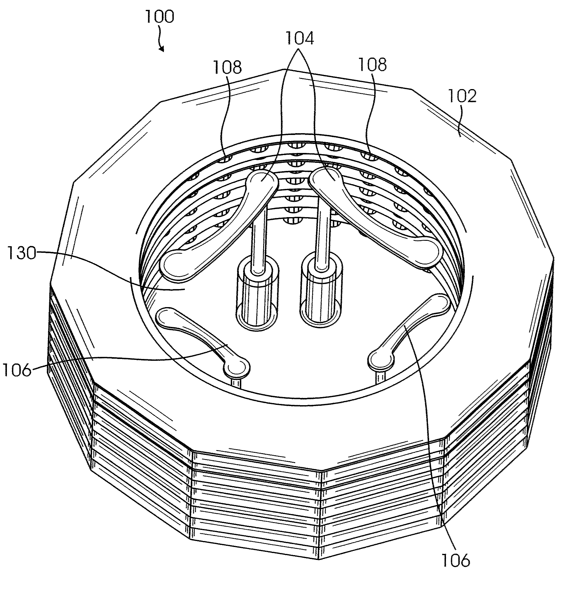
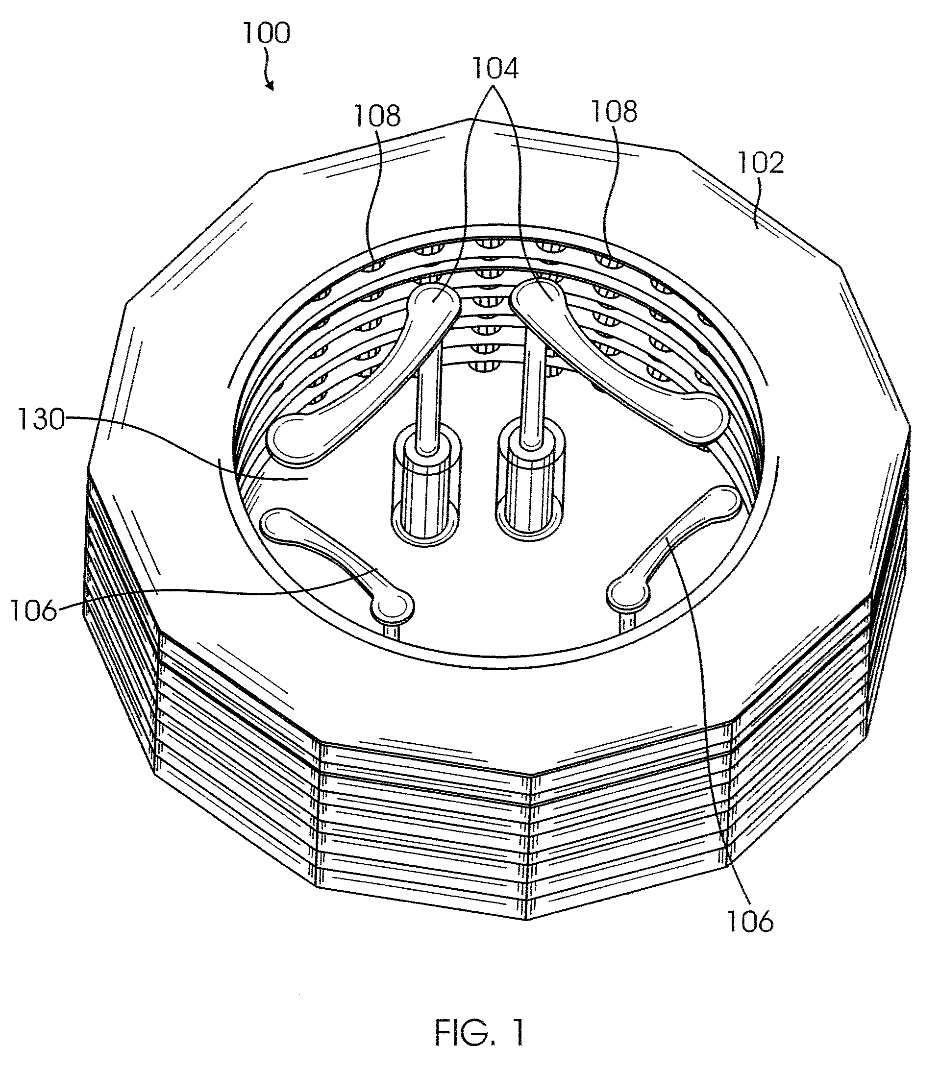
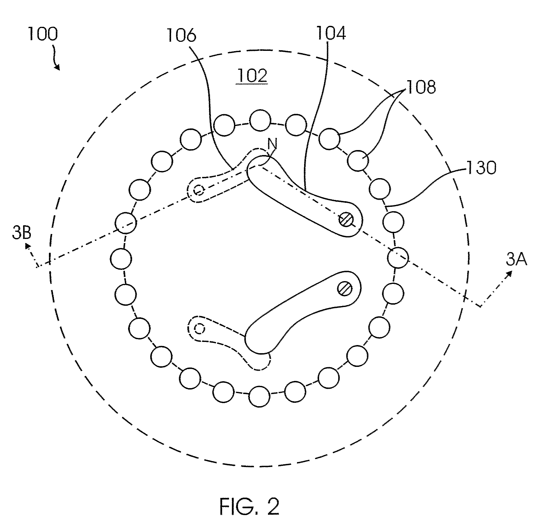
[0008]In one aspect, an Electronically Scanned Antenna (ESA) system radiating element is provided. The ESA radiating element includes at least two RF probe pairs operating in different frequency bands in a single aperture. One RF probe pair operates at a higher frequency than the other RF probe pair; the RF probe pairs generate circularly polarized waves at each frequency band.
[0009]In another embodiment, a method for operating an antenna system is provided. The method includes operating at least two RF probe pairs of an antenna element at different frequencies in a single waveguide aperture; wherein one RF probe pair operates at a higher frequency than the other RF probe pair.

Problems solved by technology

These antenna subsystems are high-cost, heavy, and space-consuming.

Method used


Image

  • Method and apparatus for antenna systems
  • Method and apparatus for antenna systems
  • Method and apparatus for antenna systems

Examples


Embodiment Construction

Definitions:

[0018]The following definitions are provided as they are typically (but not exclusively) used in relation to electromagnetic radiation, as referred to by various aspects of the present disclosure.

[0019]“Circular polarized wave” is an electromagnetic wave that is composed of radiant energy in two orthogonal planes that are 90 degrees out of phase with each other. In a circular polarized antenna, the polarization vector rotates in a circle making one complete revolution during one period of the wave.

[0020]“Frequency band” is a specific range of frequencies in the radio frequency (RF) spectrum, where each band has a defined upper and lower frequency limit, for example, K band 18-26 GHz and Ka band 26-40 GHz.

[0021]“Transverse mode” describes a radiation pattern for electromagnetic waves. When a wave travels in a waveguide, the wave's radiation pattern is determined by the properties of the waveguide. The resulting radiation intensity pattern, which is in a plane perpendicula...


PUM


Abstract

An Electronically Scanned Antenna (ESA) element and method for same, is provided. The element includes at least two RF probe pairs operating at different frequencies in a single waveguide aperture. One RF probe pair operates at a higher frequency than the other RF probe pair; and the RF probe pairs generate circular polarized waves.

Description

CROSS REFERENCE TO RELATED APPLICATIONS[0001]NoneBACKGROUND[0002]1. Field of the Invention[0003]This disclosure is related to antenna systems, and more specifically to Electronically Scanned Antenna (ESA) systems that can operate in multiple frequency bands.[0004]2. Related Art[0005]Communications systems today use plural antenna systems to communicate in multiple frequency bands. These systems often also desire the use of full-duplex operation, i.e. the ability to transmit and receive at the same time. Currently, these antenna systems use of a plurality of antenna subsystems, one for frequency of operation, and one for each transmit and receive function.[0006]As the number of frequency bands where antenna systems are operated increase, so do the number of different antenna subsystems. These antenna subsystems are high-cost, heavy, and space-consuming.[0007]It is desirable to reduce the number of antenna subsystems by combining the functions of several subsystems into a single anten...

Claims


Application Information

Patent Timeline
Patent Type & Authority Applications(United States)
IPC IPC(8): H01Q13/00
CPCH01Q9/28H01Q5/40H01Q21/26H01Q13/18
Inventor WORL, ROBERT T.
Owner THE BOEING CO
Why Eureka
Try Eureka