Method for input-signal transformation for rgbw displays with variable w color

a technology of input signal and input signal, applied in the field of additive color rgbw displays, can solve the problems of color error, loss of color saturation, simple scaling correction, etc., and achieve the effect of simple measurement, low memory, and fully automated

Inactive Publication Date: 2008-10-16
GLOBAL OLED TECH
View PDF9 Cites 96 Cited by
  • Summary
  • Abstract
  • Description
  • Claims
  • Application Information

AI Technical Summary

Benefits of technology

[0014]It is an advantage of this invention that it can transform three color-input signals to four color-output signals, even in the case that the fourth signal represents a within-gamut emitter whose color varies with intensity. It is a further advantage of this invention that it is based on first principles of color science and so does not require an adjustment step to the resulting signals. It is a further advantage of this invention that the data collection uses simple measurements, requires little memory, is fast, and can be fully automated. It is a further advantage of this invention that it gives excellent colorimetric matching between RGB and equivalent RGBW colors.

Problems solved by technology

These methods are complicated by image structure limitations because they typically involve non-continuous tone systems, but because the white of a subtractive CMYK image is determined by the substrate on which it is printed, these methods remain relatively simple with respect to color processing.
Attempting to apply analogous algorithms in continuous tone additive color systems would cause color errors if the additional primary is different in color from the display system white point.
The scaling is ostensibly to try to correct the color errors resulting from the brightness addition provided by the white, but simple correction by scaling will never restore, for all colors, all of the color saturation lost in the addition of white.
The lack of a subtraction step in this method ensures color errors in at least some colors.
Additionally, Morgan's disclosure describes a problem that arises if the white primary is different in color from the desired white point of a display device, but does not adequately solve the problem.
The method simply accepts an average effective white point, which effectively limits the choice of white primary color to a narrow range around the white point of the device.
The method of Lee et al. suffers from a similar color inaccuracy to that of Morgan.
Because of its similarity to the CMYK algorithm, it suffers from the same problem cited above, namely that a white pixel having a color different from that of the display white point will cause color errors.
While a number of other methods have addressed the problem of transforming three color-input signals to four color-output signals, e.g. Morgan et al. in U.S. Pat. No. 6,453,067, Choi et al. in US 2004 / 0222999, Inoue et al. in US 2005 / 0285828, van Mourik et al. in WO 2006 / 077554, Chang et al. in US 2006 / 0187155, and Baek in US 2006 / 0256054, these methods cannot adjust for a white emitter with variable c
gnals. This method is computationally and memory intensive, and would be slow and difficult to implement in a large d
isplay. Gathering data for the method requires manual adjustments that can be time-consuming and labor-in
tensive. It requires gathering spectral data, which is more complex and time-consuming than calorimetric meas
urements. Further, it does not mathematically guarantee a calorimetric match between a desired RGB color and the RGBW e

Method used


Image

  • Method for input-signal transformation for rgbw displays with variable w color
  • Method for input-signal transformation for rgbw displays with variable w color
  • Method for input-signal transformation for rgbw displays with variable w color

Examples


Embodiment Construction

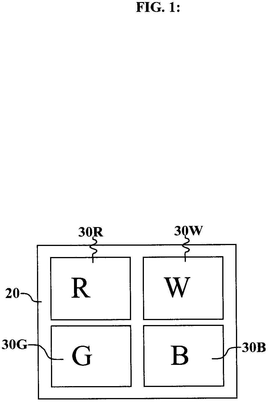
[0022]Turning now to FIG. 1, there is shown a plan view of one embodiment of an additive display device such as an OLED device that can be used in the method of this invention. Note that this method is described primarily in connection with an OLED display embodiment, but the invention is also applicable to other additive display devices such as LCDs and sequential-field color projection systems. The display includes one or more pixels 20, each of which comprises at least four light-emitting elements, which correspond to an equivalent number of primaries. Three of the primaries are gamut-defining primaries, that is, the light-emitting elements emit light that determines the range of colors that the display can produce, and are commonly red (R) primary 30R, green (G) primary 30G, and blue (B) primary 30B. The additional W primary 30W has color that varies with drive level, and therefore with intensity. In OLED systems, this color variation with drive level occurs commonly in broadban...


PUM


Abstract

A method for transforming three color-input signals (R, G, B) corresponding to three gamut-defining color primaries of a display to four color-output signals (R′, G′, B′, W) corresponding to the gamut-defining color primaries and one additional primary of the display, where the additional primary has color that varies with drive level, comprising: a) determining a relationship between drive level of the additional primary and intensities of the three gamut-defining primaries which together produce equivalent color over a range of drive levels for the additional primary; and b) employing the three color-input signals R, G, B and the relationship defined in a) to determine a value for W of the four color-output signals, and modification values to be applied to one or more of the R, G, B components of the three color-input signals to form the R′, G′, B′ values of the four color-output signals.

Description

CROSS REFERENCE TO RELATED APPLICATIONS[0001]Reference is made to commonly-assigned, co-pending U.S. Ser. No. ______ (Kodak Docket 93520) filed concurrently herewith entitled “Calibrating RGBW Displays” by Alessi et al., the disclosure of which is incorporated herein by reference.FIELD OF THE INVENTION[0002]The present invention relates to additive color RGBW displays, and in a particular embodiment specifically to RGBW OLED displays.BACKGROUND OF THE INVENTION[0003]Additive color digital image display devices are well known and are based upon a variety of technologies such as cathode ray tubes, liquid crystal modulators, and solid-state light emitters such as Organic Light Emitting Diodes (OLEDs). In a common additive color display device, a pixel includes red, green, and blue colored subpixels. These subpixels correspond to color primaries that define a color gamut. By additively combining the illumination from each of these three subpixels, i.e. with the integrative capabilities ...

Claims


Application Information

Patent Timeline
Patent Type & Authority Applications(United States)
IPC IPC(8): H04N9/30
CPCG09G3/3208G09G2300/0452H04N9/64G09G2320/0666G09G2340/06G09G2320/0242H04N9/67
Inventor HAMER, JOHN W.WHITE, CHRISTOPHER J.ALESSI, PAULA J.LUDWICKI, JOHN E.MILLER, MICHAEL E.
Owner GLOBAL OLED TECH
Why Eureka
Try Eureka