Diagnostic catheter

a diagnostic catheter and catheter technology, applied in the field of medical devices, can solve the problems of reducing the probability increasing the risk of complication to the patient, and reducing the target size, so as to improve contrast visualization, reduce the likelihood of causing trauma to the patient, and maintain structural integrity and kink resistance.

Inactive Publication Date: 2008-10-16
EDWARDS LIFESCIENCES CORP
View PDF99 Cites 38 Cited by
  • Summary
  • Abstract
  • Description
  • Claims
  • Application Information

AI Technical Summary

Benefits of technology

[0010]It is a further object of the present invention to provide a diagnostic catheter that decreases the likelihood of causing trauma to the patient during a procedure.
[0011]It is yet another object of the present invention to provide a diagnostic catheter that provides improved contrast visualization over prior art catheters.
[0012]An aspect of some preferred embodiments of the present invention relates to a diagnostic catheter having both a guidewire lumen and at least one contrast lumen. These lumens allow the user to deliver contrast to a target area within the patient without removing the guidewire.
[0013]In another aspect of some preferred embodiments of the present invention, multiple contrast lumens are included within the diagnostic catheter, maintaining structural integrity and kink resistance within the catheter body while providing a consistent flow of contrast to a target location.
[0014]In yet another aspect of some preferred embodiments of the present invention, a plurality of contrast exit ports are included along the length of the catheter body to more evenly and consistently distribute contrast into the blood stream, thereby providing improved visualization during radioscopy.

Problems solved by technology

Achieving a desired location within a patient can be difficult to attain by the feel of the catheter alone and therefore it is often necessary to visualize the anatomical shape of the vessel.
The removal of the guidewire prolongs the procedure which increases the risk of complication to the patient.
Furthermore, exchanging the guidewire may lead to a loss of the target position at the distal end of the catheter and therefore require additional searching and repositioning.
In some procedures it is not possible to reintroduce the guidewire due to spasms of vascular muscles at the target location.
In procedures where reintroduction is possible, additional trauma may result at the target location.
Additional disadvantages are also present with diagnostic catheters depending on the location being accessed.
Since the injection is made in the opposite direction of the blood flow, the infusion of contrast using this delivery method sometimes results in a resolution that may not be adequate.
In this respect, current visualization systems often fail to adequately identify anatomical obstacles within the coronary sinus such as prominent valves near the coronary sinus ostium.
Current diagnostic catheters also lack more specialized functionality such as the ability to cannulate deep within the coronary sinus, for example during a procedure to treat heart valve regurgitation.
The limitations of these devices are that since its intended use is for angiographic purposes, the tip curvature is not ideal to access the coronary sinus and thus make it difficult to cannulate.
The challenge with this technique lies with the difficulty of directing the guidewire tip into a desired side branch within the coronary sinus without causing the guidewire to become stuck or hung up.
Current angiographic catheter tips are unable to advance deep within the coronary sinus due to their necessary rigidity.
This method of exchange increases procedural times and possible risk or errors.
Additionally, when a guidewire is utilized to navigate deep within the coronary sinus, there is a risk for soft tissue damage such as tearing or piercing of the coronary sinus.

Method used


Image

  • Diagnostic catheter
  • Diagnostic catheter
  • Diagnostic catheter

Examples


Embodiment Construction

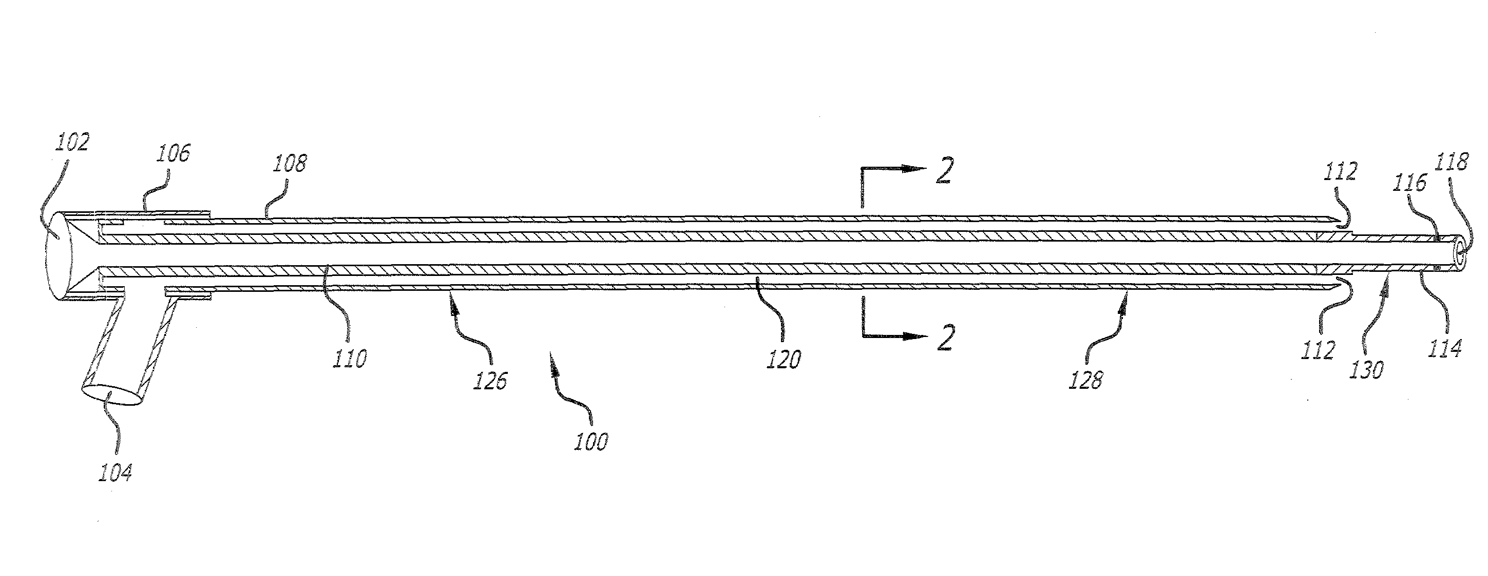
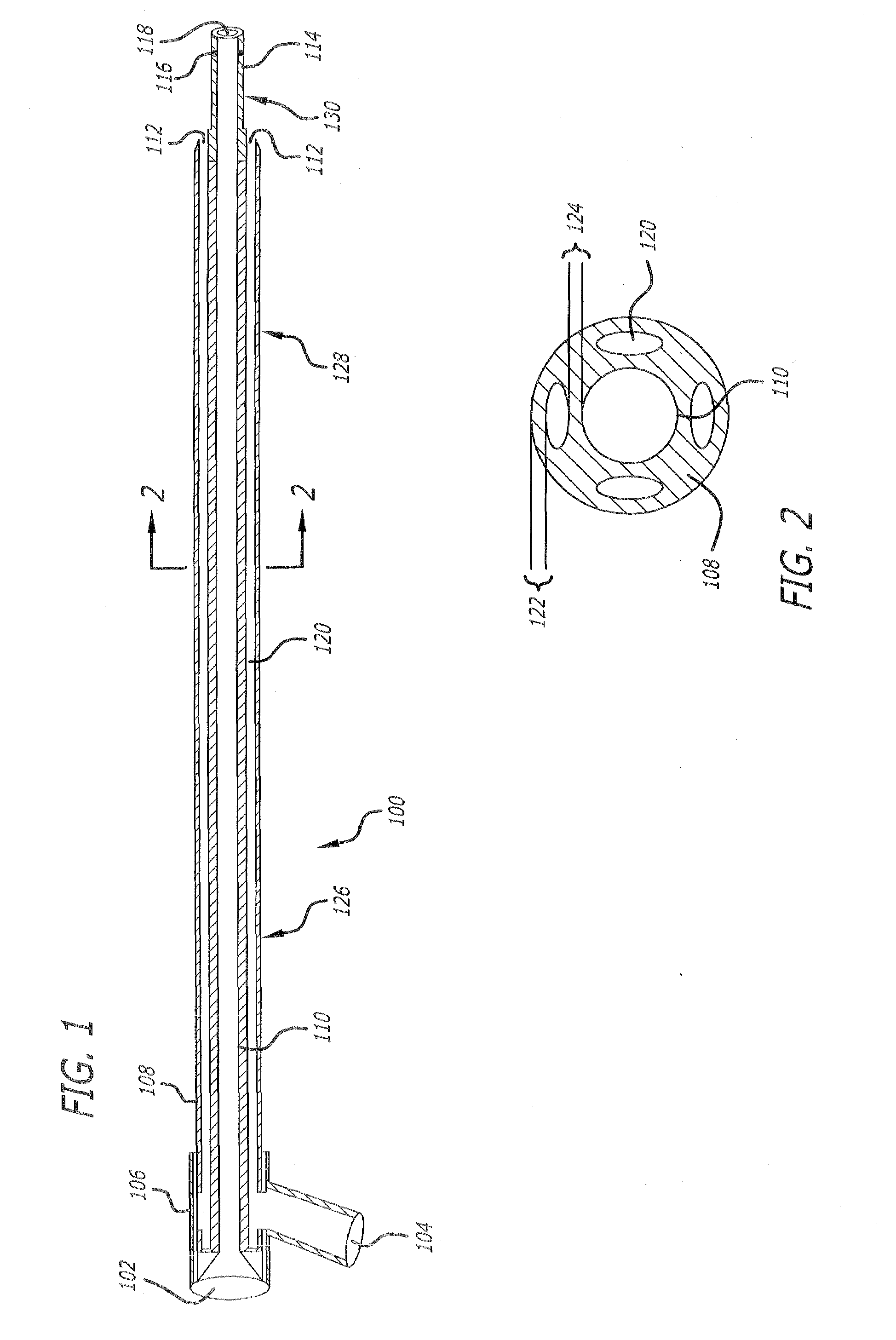
[0029]FIGS. 1 and 2 illustrate a preferred embodiment of a diagnostic catheter 100 according to the present invention. The diagnostic catheter 100 includes both a guidewire lumen 110 and four contrast lumens 120 which allow the user to deliver contrast to a target location within a patient without removing the guidewire.

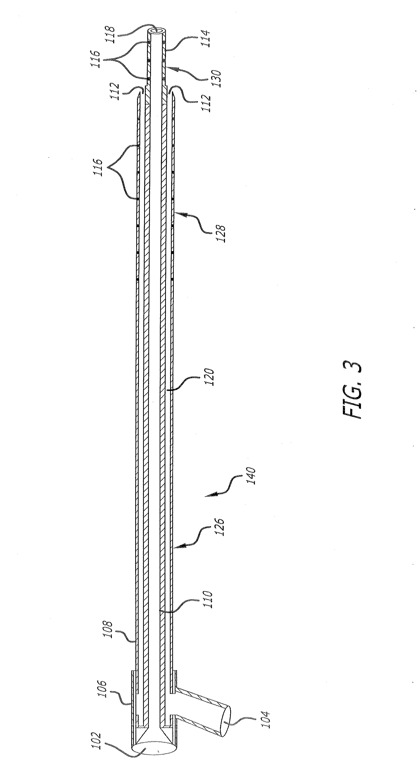
[0030]The catheter 100 has a generally elongated body 108 that includes regions 126, 128 and 130. Preferably, each region 126, 128 and 130 is progressively more flexible than the next, allowing regions 128 and 130 to better conform to the tortuous pathway of the patient's vascular system while minimizing any trauma cause by the distal end of the catheter 100. This feature is advantageous as compared with prior art measurement catheters which are more rigid and therefore may reshape the anatomy when advanced through the vascular system of a patient.

[0031]In one example, the region 126 is about 70 cm in length and composed of a high density polyethylene with a Duromete...


PUM

PropertyMeasurementUnit
lengthaaaaaaaaaa
lengthaaaaaaaaaa
inner diameteraaaaaaaaaa

Abstract

A diagnostic catheter having both a guidewire lumen and at least one contrast lumen is disclosed. In one embodiment, the contrast lumens allow the user to deliver contrast to a target area within the patient without removing the guidewire. Preferably, a plurality of contrast exit ports are included along the length of the catheter body to evenly and consistently distribute contrast into the blood stream, thereby providing improved visualization during radioscopy.

Description

FIELD OF THE INVENTION[0001]The present invention relates to medical devices and, more particularly, to an improved diagnostic catheter and method of use.BACKGROUND[0002]Catheters are used in a number of medical procedures within various conduits of the body for the purposes of diagnosis and treatment. Typically, catheters have an elongated body with at least one interior lumen which is sized to accept a guidewire. The guidewire is usually inserted first into a patient so that a distal end of the guidewire is positioned at or near a desired target location within the patient. The catheter lumen is fed on to the guidewire, allowing a distal end of the catheter to advance to the target location within the patient.[0003]For example, angioplasty generally includes the steps of inserting a guidewire through a vascular access needle into the femoral or jugular artery or vein and manipulating the external proximal end of the guidewire to advance the distal end of the guidewire through the ...

Claims


Application Information

Patent Timeline
Patent Type & Authority Applications(United States)
IPC IPC(8): A61M25/01
CPCA61M25/0041A61M25/0045A61M25/007A61M25/04A61M25/1002A61M25/1011A61M31/005A61M2025/0004A61M2025/0036A61M2025/0039A61M2025/004
Inventor BOURANG, HENRYWERTENBERG, WILLIAM R.HOSMER, RONALD J.BULLER, CHRISTOPHERNGUYEN, DUY
Owner EDWARDS LIFESCIENCES CORP
Why Eureka
Try Eureka