Explosion protection system with integrated emission control device

a technology of emission control device and explosion protection system, which is applied in the direction of exhaust treatment, engine components, mechanical equipment, etc., can solve the problems of gases and/or flammable materials present in the area to ignite and/or explode, severe restrictions on their use, and relatively complex prior art systems

Active Publication Date: 2008-10-23
MIRETTI SPA
View PDF9 Cites 29 Cited by
  • Summary
  • Abstract
  • Description
  • Claims
  • Application Information

AI Technical Summary

Benefits of technology

[0006]Systems embodying the invention include an exhaust system mounted via explosion proof flanges to the engine cylinder head. The exhaust system includes a flame-arrester-oxidizing device comprising a duct having an input end and an output end and a passageway between the input and output ends for passing the exhaust gases. An oxidizing and filtering device comprising metal foils coated by a noble metal (e.g., platinum, or the like) is firmly and securely affixed across the passageway. In addition, an insulator layer is mounted over the external wall of the duct. A jacket is mounted over the insulator through which a coolant (water or the like) can pass to cool the external surface of the system, in contact with the atmosphere, to a temperature (e.g., 90 degrees centigrade) below a prescribed level. At the same time, the insulator layer insures that the coolant does not lower the temperature within the duct's passageway to a value which would prevent oxidation. By maintaining the temperature within the duct at an elevated temperature, the exhaust fumes and pollutants from the engine, passing through and along the metal foils, are oxidized resulting in mostly water vapour and gases being emitted at the exhaust output of the device. Thus, the flame arrester oxidizing device of the invention functions as a remover of pollutants and is generally self cleaning. This eliminates the need for frequent cleaning and maintenance present in the prior art.

Problems solved by technology

The heat generated by the engines and the exhaust fumes of these pieces of equipment may cause the gases and / or flammable material present in the area to ignite and / or explode.
Known prior art systems are relatively complex and the need to perform frequent cleaning and maintenance imposes severe restrictions on their use.

Method used


Image

  • Explosion protection system with integrated emission control device
  • Explosion protection system with integrated emission control device
  • Explosion protection system with integrated emission control device

Examples


Embodiment Construction

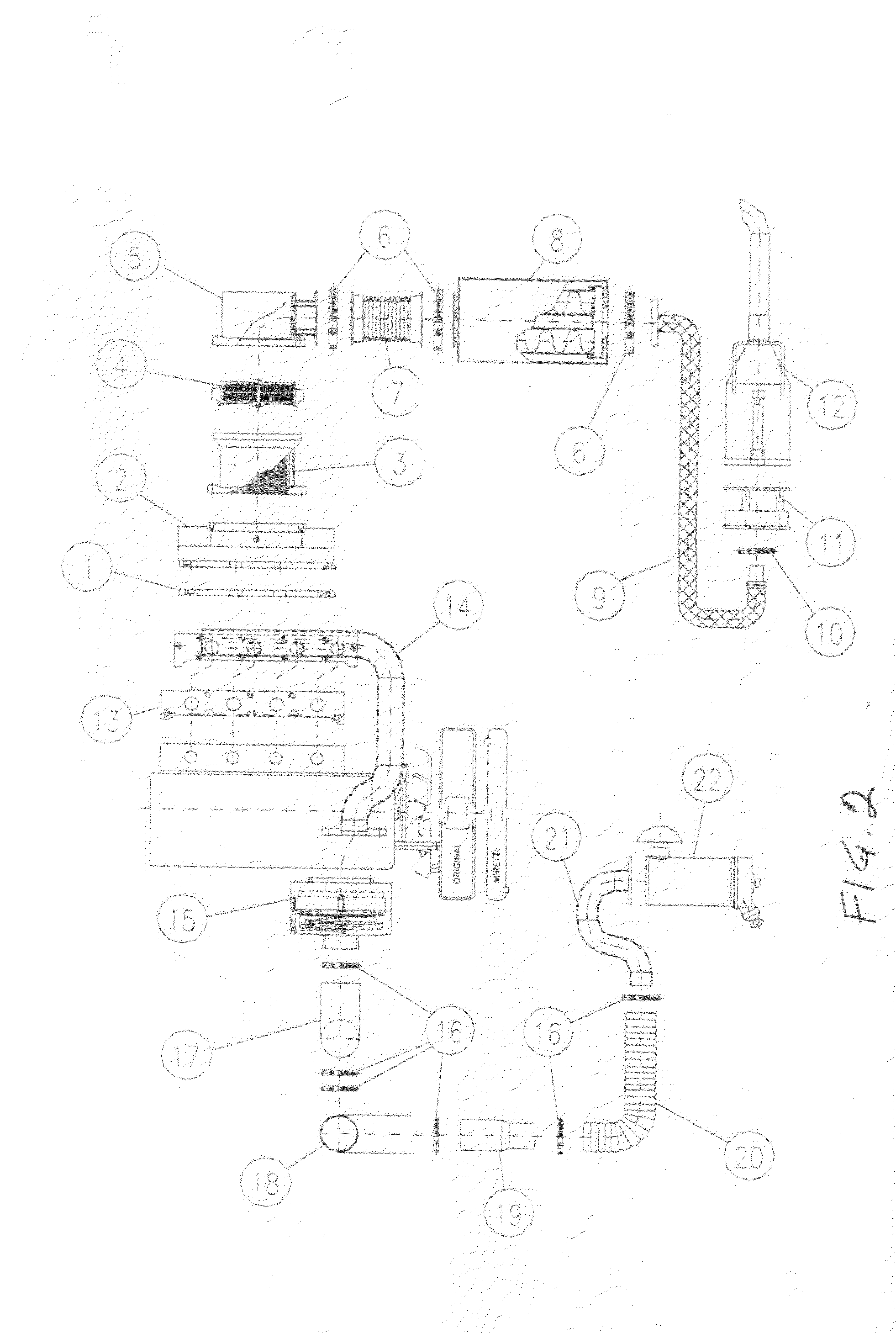
[0018]Selected components of the intake / exhaust assembly shown in FIG. 2 are identified by respective reference characters whose general, brief, descriptions are given in Table I, attached. The exhaust portion of the system shown in FIG. 2 includes an exhaust engine sealed flange 1 coupled to a primary heat exchanger 2 which in turn is coupled to a platinum coated preliminary flame arrestor 3 which in turn is coupled to a secondary flame arrestor / heat exchanger 4 which is coupled via a flow deflector 5, clamp 6 and flexible pipe 7 to an additional (third) heat exchanger (integrated spark arrestor) 8 which exhausts via flanged pipe 9 and components 10 and 11 to, and through, particle filter 12 to the atmosphere external to the exhaust system.

[0019]The intake portion of the system shown in FIG. 2 includes an air filter 22 whose intake is coupled via pipes, elbows and clamps 21, 20, 19, 18, 17 and 16 to intake flame arrestor and intake shut down valve 15. The flow out of component 15 i...


PUM


Abstract

The exhaust system of an internal combustion engine includes a duct having an input end coupled to the engine for passing and processing the exhaust gases and fumes emitted by the engine such that the duct functions as an anti-explosion and fire arrester device. The duct includes a reinforced filter structure securely and firmly mounted within and across the duct opening. The filter structure is coated with a noble metal to enhance oxidation of the gases and fumes passing through the duct. An insulator layer is attached about and along the outer surface of the duct and a jacket for carrying a coolant is mounted above and about the insulator layer. The insulator layer isolates the coolant from the duct to ensure that the temperature on the external side of the jacket is less than a predetermined value. Simultaneously, the insulator layer isolates the duct from the coolant to enable the temperature within the duct to have a sufficiently high value to sustain oxidation of the gases and fumes. The input end of the duct may be connected to the engine via a first heat exchanger and the exhaust end of the duct may be connected by additional heat exchangers to the exhaust system output.

Description

[0001]This application claims priority from provisional application Ser. No. 60 / 880,235 filed Jan. 12, 2007 for Explosion Protection System with Integrated Emission Control DeviceBACKGROUND OF THE INVENTION[0002]This invention relates to explosion proof exhaust systems and in particular to an explosion poof exhaust system which includes a flame arrester integrated with an emission control device.[0003]Many pieces of equipment (e.g., internal combustion operated industrial machinery) have to be operated in areas where gases and flammable substances are present. The heat generated by the engines and the exhaust fumes of these pieces of equipment may cause the gases and / or flammable material present in the area to ignite and / or explode. It is therefore necessary to reduce the external surface temperature of the pieces of equipment and to prevent sparks / flames from being emitted out of the exhaust. It is further necessary and / or desirable to reduce the pollutants emitted by the pieces o...

Claims


Application Information

Patent Timeline
Patent Type & Authority Applications(United States)
IPC IPC(8): F01N3/022F01N13/14
CPCF01N3/0205F01N3/035F01N3/043F01N3/06F01N3/2889F01N13/002F01N13/14F01N2240/02F01N2260/02F01N2330/02F01N2510/06F01N2590/00
Inventor MIRETTI, ANGELO B.
Owner MIRETTI SPA
Why Eureka
Try Eureka