Humidity sensor

a sensor and humidity technology, applied in the field of humidity sensors, to achieve the effect of intial detection accuracy

Active Publication Date: 2008-10-23
DENSO CORP
View PDF3 Cites 26 Cited by
  • Summary
  • Abstract
  • Description
  • Claims
  • Application Information

AI Technical Summary

Benefits of technology

[0007]In the above sensor, even when the sensor is used for a long time, initial detec

Problems solved by technology

Thus, it is required for the humidity sensor to maintain the detection accuracy for a long time.

Method used


Image

  • Humidity sensor
  • Humidity sensor
  • Humidity sensor

Examples


first embodiment

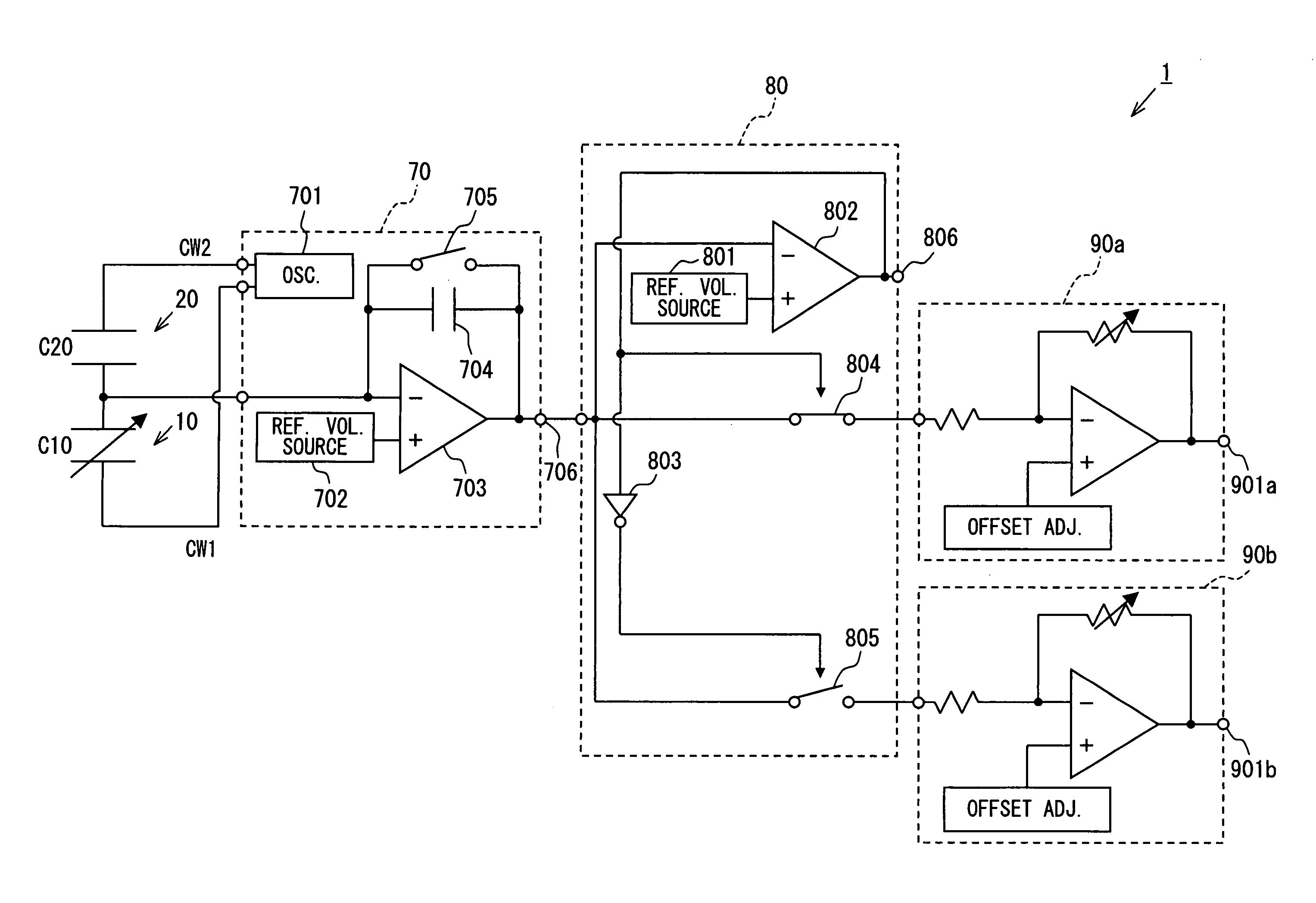
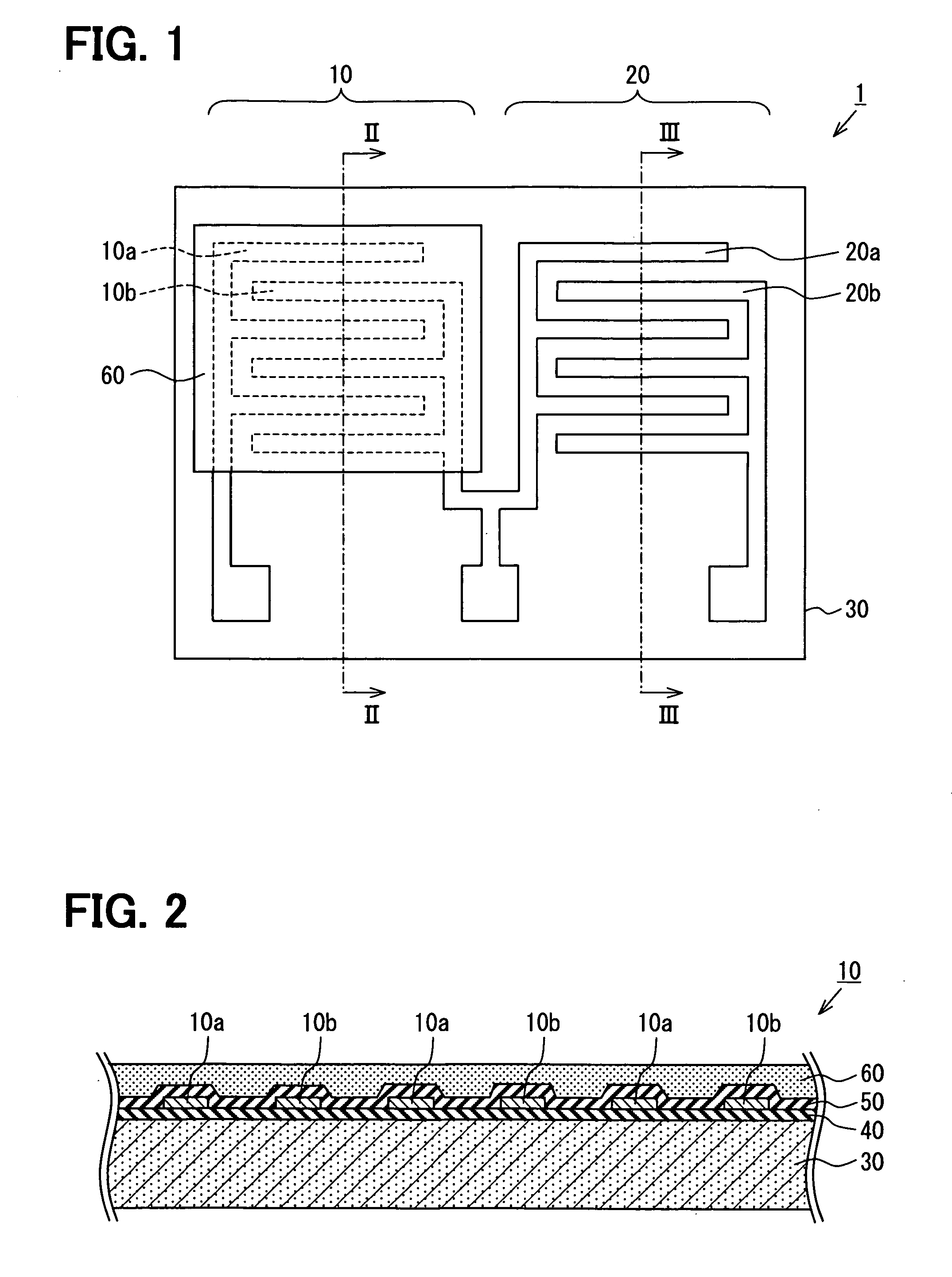
[0027]FIGS. 1-7 show a humidity sensor 1 according to a first embodiment. The humidity sensor is, for example, a capacitive humidity sensor for detecting humidity based on dielectric constant of a humidity sensitive film.

[0028]The capacitive humidity sensor 1 includes a first sensor element 10 as a humidity sensor element and a second sensor element 20 as a second capacitive element.

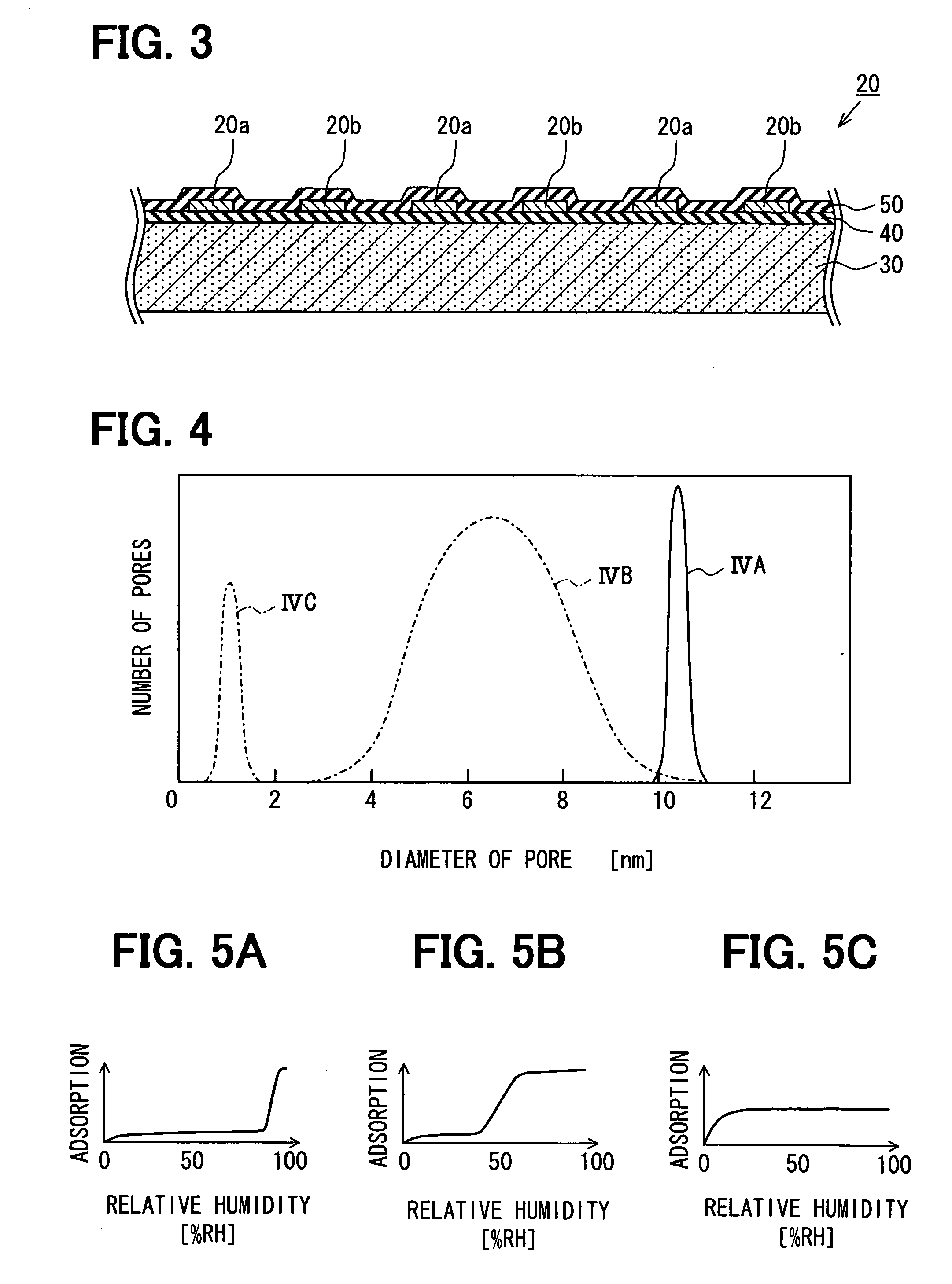
[0029]As shown in FIGS. 2 and 3, the first and second sensor elements 10, 20 are formed on, for example, the same semiconductor substrate 30 made of silicon. An insulation film 40 made of silicon oxide is formed on the surface of the substrate 30. Two pairs of electrodes 10a, 10b, 20a, 20b for detecting relative humidity in atmosphere around the sensor 1 are formed on the insulation film 40, respectively. The electrodes 10a, 10b, 20a, 20b are made of metal such as aluminum, and separated from each other by a predetermined distance. The electrodes 10a, 10b, 20a, 20b are disposed on the same plane. The ele...

second embodiment

[0068]FIG. 13 shows a humidity sensor 2 according to a second embodiment. The humidity sensor 2 includes a cantilever 62 as a humidity sensitive member, a support member 31, a strain gauge 11 and a processing circuit (not shown). The support member 31 supports the cantilever 62 at one portion in such a manner that the cantilever 62 is capable of vibrating. The cantilever 62 is made of humidity sensitive material, and is capable of vibrating with a resonant frequency in accordance with weight of moisture adsorbed in the humidity sensitive material. The strain gauge 11 as a detector outputs an electric signal to the processing circuit, the electric signal corresponding to amplitude of the cantilever 62. The processing circuit processes the electric signal from the strain gauge 11.

[0069]The cantilever 62 has a rectangular shape and protrudes from a sidewall of the support member 31. The cantilever 62 is capable of vibrating in an up-down direction around a support portion of the suppor...


PUM


Abstract

A capacitive humidity sensor includes: a humidity sensing element with a humidity sensitive film and electrodes; and a processing circuit. The film has a dielectric constant variable in accordance with moisture. The electrodes detect capacitance of the film and outputs a signal corresponding to the capacitance. The processing circuit processes the signal. The film is made of inorganic material having fine pores for adsorbing the moisture. A diameter of the fine pores is set to be a predetermined diameter so that capillary tube aggregation phenomenon occurs at a predetermined relative humidity. The capacitance of the film has a change rate with respect to the relative humidity. The change rate in case of the relative humidity higher than the predetermined relative humidity is larger than that in case of the relative humidity lower than the predetermined relative humidity.

Description

CROSS REFERENCE TO RELATED APPLICATION[0001]This application is based on Japanese Patent Application No. 2007-112136 filed on Apr. 20, 2007, the disclosure of which is incorporated herein by reference.FIELD OF THE INVENTION[0002]The present invention relates to a humidity sensor.BACKGROUND OF THE INVENTION[0003]A humidity sensor for detecting humidity of atmosphere around the sensor is disclosed in, for example, JP-A-2002-243690 corresponding to U.S. Pat. No. 6,580,600. The sensor includes a semiconductor substrate, a silicon oxide film on the substrate, a pair of electrodes disposed on the same plane of the silicon oxide film so as to separate from each other, a silicon nitride film covering the electrodes, and a humidity sensitive film disposed on the silicon nitride film. The humidity sensitive film covers the electrodes and is disposed between the electrodes. A capacitance between the electrodes is changeable in accordance with humidity of atmosphere around the sensor. Based on ...

Claims


Application Information

Patent Timeline
IPC IPC(8): G01N27/22
CPCG01N27/225
Inventor ISOGAI, TOSHIKIITAKURA, TOSHIKAZU
Owner DENSO CORP
Why Eureka
Try Eureka