Tracheal Cannula

a tracheal cannula and tracheal tube technology, applied in the field of tracheal tubes, can solve the problems of affecting the caretaker's breathing, affecting the smooth breathing of the patient, etc., and achieve the effect of improving the response of the tracheal tube to the emergence of phlegm and easy covering

Inactive Publication Date: 2008-10-23
KOKEN CO LTD
View PDF6 Cites 32 Cited by
  • Summary
  • Abstract
  • Description
  • Claims
  • Application Information

AI Technical Summary

Benefits of technology

[0016]It is preferable with respect to the tracheal cannula according to the present invention that the suction opening of the phlegm suction path is located on the side of the cuff with respect to the opening formed on the trachea side of the distal end of the breathing path. In this case, a wall of the opening on the trachea side of the breathing path is formed between the distal end of the tracheal cannula and the phlegm suction opening. As a result, in sucking phlegm, even if a smallest part of phlegm accumulated in the trachea contacts the formed wall of the opening on the trachea side before the substantially entire phlegm suction opening is covered up, the phlegm will extend along the surface of that wall. As a matter of course, there is a part of phlegm then moving toward the phlegm suction opening. Therefore, the phlegm suction opening may more easily be covered up than in the case of the tracheal cannula of the prior art in which the opening of the breathing path on the trachea side and the opening of the pathway on the trachea side are located in a same plane perpendicular to the length direction of the breathing path. By this, phlegm can be sucked positively with a smaller amount of phlegm produced than that in the case of the prior art, and the phlegm in the trachea can be sucked promptly. Thus, the response of the tracheal cannula to emergence of phlegm can be improved.
[0017]With respect to the tracheal cannula of the present invention, it is preferable to form a further phlegm suction opening on a partition wall between the breathing path and the suction path so as to communicate the both paths to each other. In this case, even if suction of phlegm is made through the phlegm suction opening directly connecting the phlegm suction path and the trachea in such a condition that the opening is tightly appressed to the inner wall of the trachea (i.e., futile suction), that part of the inner wall of the trachea is not absorbed into the phlegm suction opening at the distal end of the cannula. This is because there is provided another phlegm suction opening on the partition wall of the phlegm suction path on the breathing path side, which functions as a relief valve. In sucking phlegm, the phlegm suction opening formed in the partition wall is covered up when phlegm flows into the suction path through the phlegm suction opening formed in the wall of the suction path on the side of the inner wall of the trachea, since a membrane of phlegm forms in the suction path. Therefore, the power of suction of phlegm through the phlegm suction opening on the side of the inner wall of the trachea is not to be decreased because of the phlegm suction opening formed in the partition wall. Further, in discharging air with the use of the artificial respirator, there may be a concern that the phlegm flows into the breathing path of the tracheal cannula to interfere with smooth breathing. However, since phlegm accumulated around the distal end of the breathing path of the tracheal cannula is sucked through the phlegm suction opening formed at the distal end of the phlegm suction path on the partition wall, the phlegm can readily be removed if ever the phlegm has flowed into the breathing path. Thus, there is practically no danger of interference of smooth breathing.
[0018]With respect to the tracheal cannula of the present invention, the distal end of the phlegm suction path may either be closed or left open so that it can be connected to the trachea. Further, a region of the partition wall between the breathing path and the suction path may end up before the distal end of the trachea cannula (between the basal end and the distal end) to form a communication space in which the distal ends of the breathing path and the suction path are communicated with each other and which, in turn, is to be communicated with the trachea.
[0019]Preferred embodiments of the present invention will be explained below in further detail with reference to the drawings.

Problems solved by technology

With this treatment method, however, the caretaker is obliged to work any time day and night, thereby imposing an excessive burden upon the caretaker.
(1) Suction of phlegm is delayed in the case where phlegm in the trachea is directly sucked through the pathway as a phlegm suction path instead of inserting the suction catheter through pathway. This is because the opening of the pathway on the trachea side (the phlegm suction opening) is located in the same plane (cross section) as the opening of the breathing path on the trachea side. In other words, as long as the opening of the pathway on the trachea side is not entirely covered with phlegm, suction is mainly made of air inside the respiratory tract or the lung, while substantially no phlegm can be sucked.
(2) Further, because the phlegm suction opening at the distal end of the suction catheter is located on the opposite side of the inner wall on the trachea side (on the inner side of the curvature) when fixed, suction of phlegm is not started until the substantially entire distal end of the suction catheter inserted into the trachea is covered with phlegm. Consequently, it is only after a certain amount of phlegm is accumulated in the trachea that the suction of phlegm is started.
(3) Moreover, if phlegm partly flows into the breathing path of the tracheal cannula during air discharge made by the artificial respirator, there is concern that smooth breathing may be disturbed because said part of phlegm having flowed into the breathing path cannot be removed.

Method used


Image

  • Tracheal Cannula
  • Tracheal Cannula
  • Tracheal Cannula

Examples


first embodiment

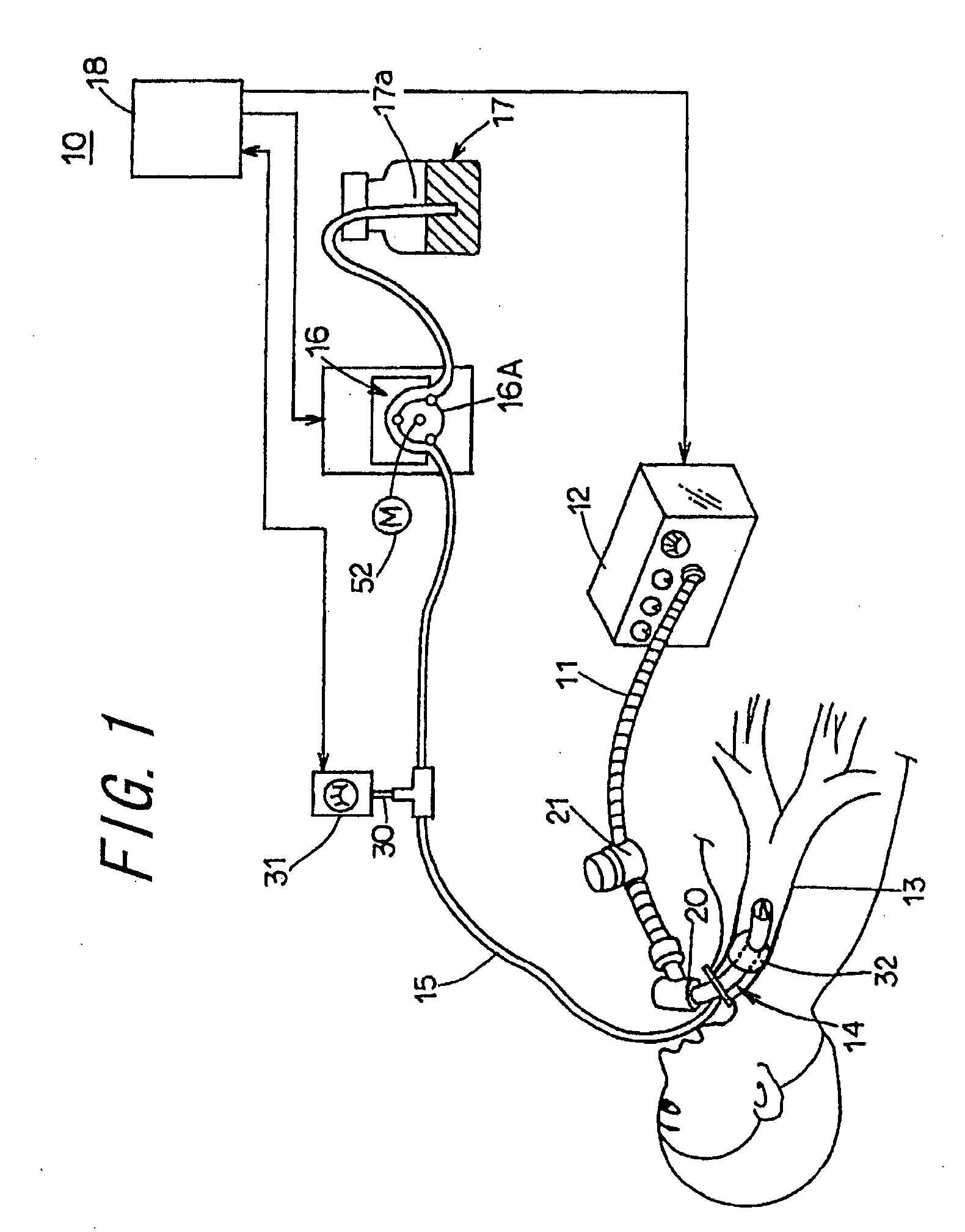
[0028]In FIG. 1 is shown an artificial respiration system represented as a whole by reference numeral 10, and applied with a tracheal cannula 14 according to the present invention. The artificial respiration system 10 comprises an artificial respirator 12 communicated with a breathing tube 11 for supplying and discharging air, the above-mentioned tracheal cannula 14 which is to be inserted into a patient's incised trachea 13, a phlegm suction machine 16 communicated with a suction tube 15 for sucking phlegm accumulated in the trachea 13, and a phlegm collection bottle 17. The artificial respiration system 10 further comprises a control box 18 including a sequencer, timer, etc., for controlling an amount of inlet flow into the phlegm suction machine 16 by regulating a suction pressure of the phlegm suction machine 16, based on an inner pressure of the suction tube 15.

[0029]The artificial respirator 12 has a configuration known, per se, in which breathing is secured by alternately put...

second embodiment

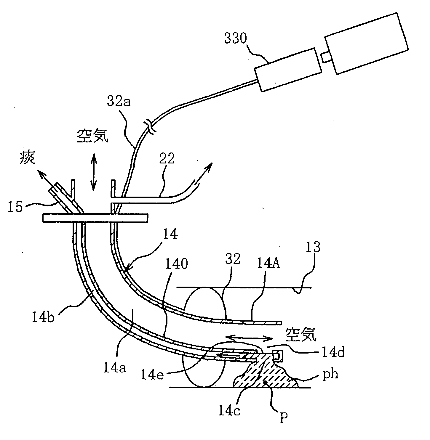
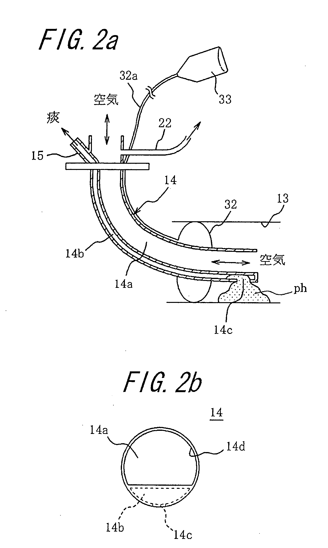
[0055]With the embodiment of FIG. 6 having such configuration, phlegm is sucked through the phlegm suction opening 14c on the bottom side, in the same manner as in the above embodiments. In addition, since there is formed a large cutaway, i.e. another phlegm suction opening on the upper side (equivalent to the phlegm suction opening 14e in the case of the second embodiment), or a slit at the distal end of the partition wall, phlegm in the breathing path 14a can be sucked from this opened part (i.e., the part where it is communicated with the distal end opening 14d of the main body 14A of the tracheal cannula). It is easier to form a slit at the distal end of the partition wall than to form a cutaway. Other configurations and operations are the same as those in the above-described embodiments.

fourth embodiment

[0056]In FIG. 7 is illustrated a tracheal cannula according to the present invention. In this embodiment, a part of the distal end of the phlegm suction path 14b in the tracheal cannula 14 (a part of the bottom of the main body 14A of the cannula) is cutaway to form an opening. Although the breathing path 14a and the suction path 14b are separated by the partition wall 140, the both paths are communicated with each other through the phlegm suction opening 14e formed at the distal end of the partition wall 140. At the same time, on the bottom side of the distal end of the phlegm suction path 14b is formed an opening or an opened part, which is located below the distal end of the partition wall 140 so as to communicate the phlegm suction path 14b with the trachea. This opening or opened part 14c′ functions as an equivalent of the phlegm suction path 14c in the above-described embodiments, so that phlegm outside the main body 14A of the cannula and on the bottom of the trachea can be s...


PUM


Abstract

A tracheal cannula of the invention includes a breathing path for supplying and discharging air formed between a basal end for connection with a breathing tube extending from an external artificial respirator and a distal end for insertion into a patient's trachea, and a trachea side opening formed at the distal end of the breathing path. Besides and along the breathing path, a suction path is provided for sucking phlegm accumulated in the patient's trachea. A phlegm suction opening is formed in a region of a wall of the suction path on the side of the inner wall of the trachea between the distal end of the breathing path and a cuff, the phlegm suction opening facing the inner wall of the trachea.

Description

FIELD OF THE INVENTION[0001]The present invention relates to a tracheal cannula used for providing artificial respiration on a patient, and particularly to a tracheal cannula with which phlegm accumulated in the patient's trachea can effectively be sucked. The tracheal cannula according to the present invention relates not only to a tracheotomy tube inserted into the trachea through an opening formed in the patient's trachea in a tracheotomy operation, but also to a cannula for artificial respiration that is orally inserted into the trachea.BACKGROUND OF THE INVENTION[0002]A technique for providing artificial respiration with the use of an artificial respirator has been developed so far, in which a tracheal cannula is inserted into an incised trachea, and a breathing tube extended from the artificial respirator is communicated via an adapter with the tracheal cannula. Inside the tracheal cannula is formed a breathing path for supplying and discharging air. When providing artificial ...

Claims


Application Information

Patent Timeline
Patent Type & Authority Applications(United States)
IPC IPC(8): A61M16/04
CPCA61M16/04A61M16/0484A61M2016/0027A61M16/0486
Inventor YAMAMOTO, MAKOTOTOKUNAGA, SHUICHI
Owner KOKEN CO LTD
Why Eureka
Try Eureka