Electromagnetic Wave Absorber

a technology of electromagnetic absorber and absorber, which is applied in the direction of magnetic/electric field screening, electrical equipment, and antennas, etc., can solve the problems of deterioration of transmission speed, interference with other wavelengths, and interference with electromagnetic waves, and achieve the effect of small displacement and high peak value of absorption amoun

Inactive Publication Date: 2008-10-23
NITTA CORP
View PDF6 Cites 32 Cited by
  • Summary
  • Abstract
  • Description
  • Claims
  • Application Information

AI Technical Summary

Benefits of technology

[0008]An object of the invention is to provide an electromagnetic wave absorber that has high peak value of absorption amount of an electromagnetic wave or is capable of absorbing electromagnetic waves of a plurality of frequencies, and is small in displacement between frequencies where peaks of absorption amount are reached, which displacement is caused by difference of polarization directions of electromagnetic waves.

Problems solved by technology

When a plurality of wireless LAN systems is set up in close vicinity each other or in an environment where a wireless LAN is set up a microwave oven or an antitheft security system that utilizes a wireless communication technology is used, as the result of usage of electromagnetic waves in the same frequency band, a problem of electromagnetic wave interference (interference with other wavelength) may be caused.
Separately therefrom, a problem of an error in transmission due to a reflection wave (problem of multipath, self-interference) may be caused.
Specifically, the deterioration in a transmission speed between units that make use of the wireless technology and an increase in a BER (Bit Error Rate), that is, the deterioration of a communication environment is caused.
There is concern over adverse affect on electronic units as well, and, in the worst case, a device may malfunction.
However, when the polarization dependency of the pattern is large, it becomes difficult to make correspond to an electromagnetic wave of a frequency to be absorbed.
That is, there is a problem in that, owing to a shape of a pattern, depending on a TE wave, TM wave, an electromagnetic wave entering from an arbitrary angle therebetween or a circularly polarized wave, the electromagnetic wave absorption characteristics, in particular, an absorption frequency varies, accordingly a problem in that the electromagnetic wave absorption characteristics have the polarization dependency.

Method used


Image

  • Electromagnetic Wave Absorber
  • Electromagnetic Wave Absorber
  • Electromagnetic Wave Absorber

Examples


Embodiment Construction

[0057]Now referring to the drawings, preferred embodiments of the invention are described below.

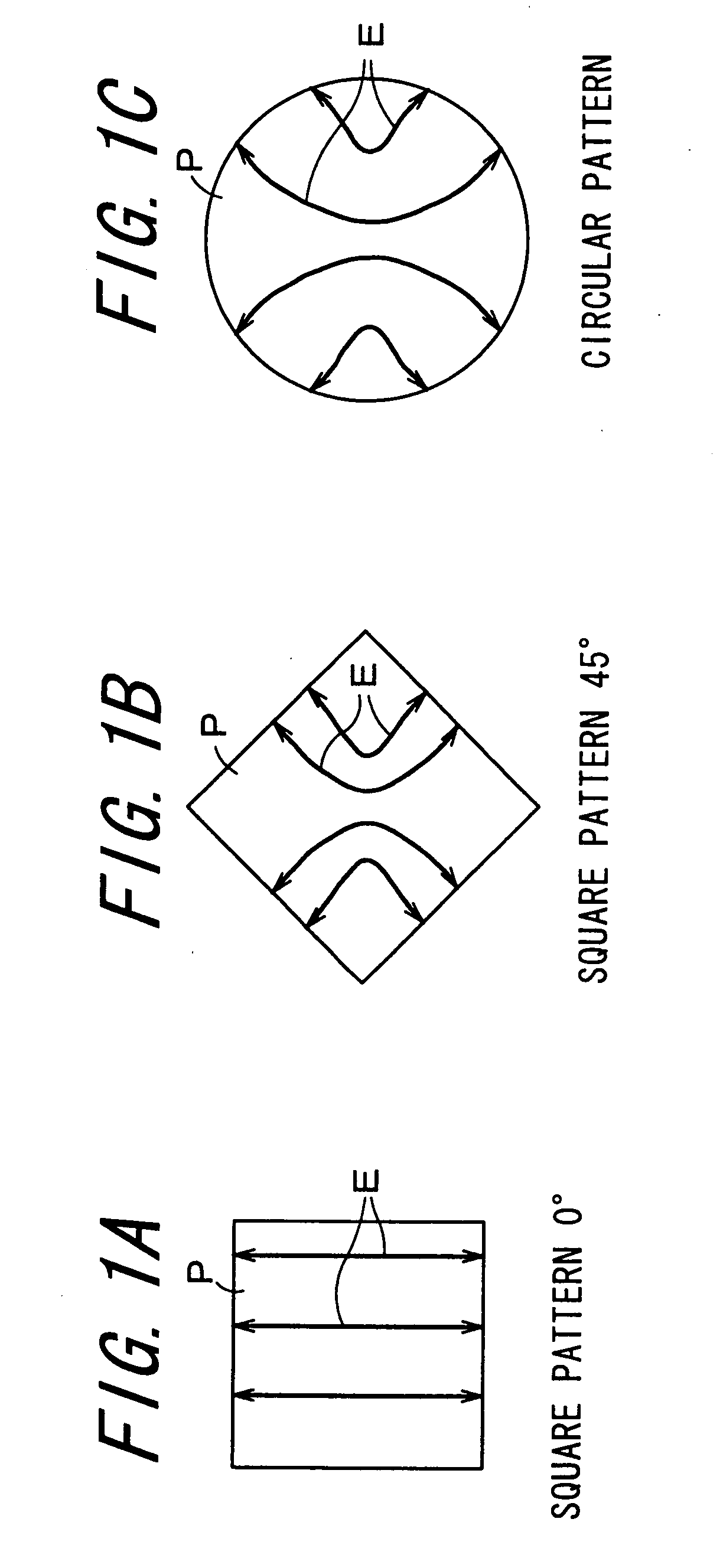
[0058]FIG. 1 is a front view of a pattern P showing an influence that a direction of the pattern P affects on an electric field generated in the pattern P when in the pattern P an electromagnetic wave that is a TE wave is received. FIG. 1A shows how an electric field is generated when a square pattern P is placed in such a positional relationship that two sides thereof are in parallel with a direction of an electric field in an electromagnetic wave (hereinafter, in some cases, referred to as “polarization direction”), FIG. 1B shows how an electric field is generated when a pattern P is displaced by 45° from the positional relationship of FIG. 1 and FIG. 1C shows how an electric field is generated in a case of a circular pattern P. The positional relationship of FIG. 1A is a positional relationship of a square pattern P having sides in parallel with or vertical to a direction of an electri...


PUM


Abstract

A conductive pattern basically has a substantially polygonal outline shape which is a polygon and can have a high peak value of the electromagnetic wave absorption amount as compared to a case when the conductive pattern has a circular outline shape. Thus, the conductive pattern is basically a polygon and at least one corner portion is shaped in curve. This reduces or even minimizes the shift of the frequency at which the absorption amount becomes a peak value by the polarization direction of the electromagnetic wave. Accordingly, in at least one embodiment, it is possible to realize an electromagnetic absorber having an excellent electromagnetic wave absorption characteristic exhibiting a high peak value of the absorption amount of the electromagnetic wave and a small shift of frequency at which the absorption amount becomes a peak value by the polarization direction of the electromagnetic wave.

Description

TECHNICAL FIELD[0001]The present invention relates to an electromagnetic wave absorber that catches an electromagnetic wave and absorbs it.BACKGROUND ART[0002]When a LAN (Local Area Network) of a computer network is set up, a wireless LAN that uses microwaves is utilized and thereby a communication system more flexible and higher in the mobility is set up. Furthermore, a communication service that communicates by wireless between a wide network system or an exchange network called FWA (Fixed Wireless Access) and communication apparatus that a user operates has started. That is, a wireless communication system is being utilized more and more familiarly. Still furthermore, a short distance wireless technology called Bluetooth representative of a WPAN (Wireless Personal Area Network) is utilized as an alternative technology of a wire / cable technology. In years to come, a communication system that uses a portable telephone that can verbally communicate due to a wireless LAN called a VoW...

Claims


Application Information

Patent Timeline
Patent Type & Authority Applications(United States)
IPC IPC(8): H05K9/00
CPCH01Q17/00H01Q17/007H05K9/0088H01Q15/0013
Inventor MATSUSHITA, MASATOYOSHIDA, TAKAHIROGO, HARUHIDEKIYOHARA, YOSHIHARUMAEZAWA, MAKOTOSATO, SHINICHI
Owner NITTA CORP
Why Eureka
Try Eureka