Liquid dispensing device

Inactive Publication Date: 2008-10-23
REELICK EUGENE A
View PDF30 Cites 4 Cited by
  • Summary
  • Abstract
  • Description
  • Claims
  • Application Information

AI Technical Summary

Benefits of technology

[0006]The primary object of the present invention is to provide a liquid dis

Problems solved by technology

However, many individuals find the use of such reservoirs difficult as the user must carry the reservoir over the entire area to be sprayed and must repeatedly pump the reservoir to provide a predetermined amount of pressure to spray the liquid.
Moreover, because the reservoir is f

Method used


Image

  • Liquid dispensing device
  • Liquid dispensing device
  • Liquid dispensing device

Examples


Embodiment Construction

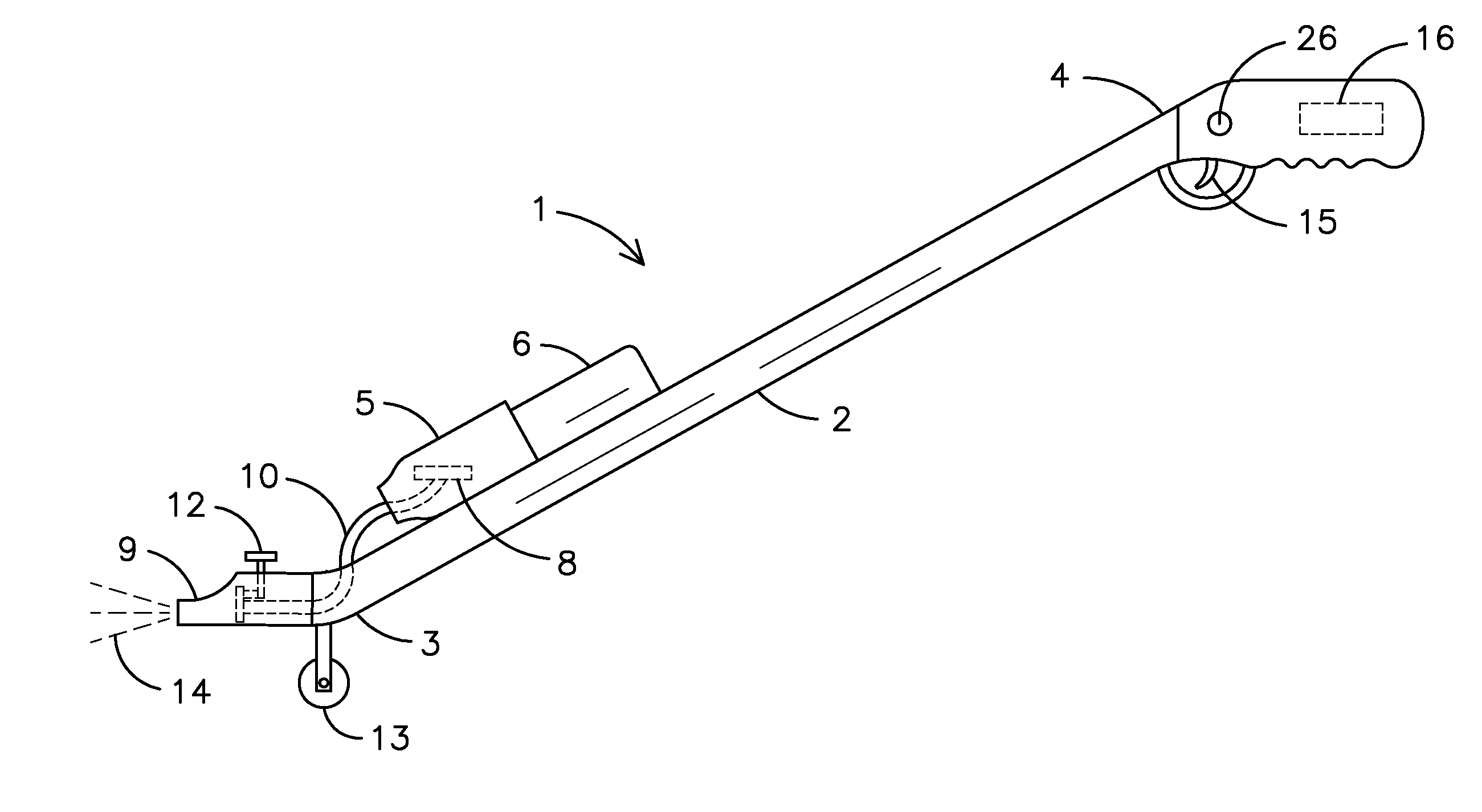
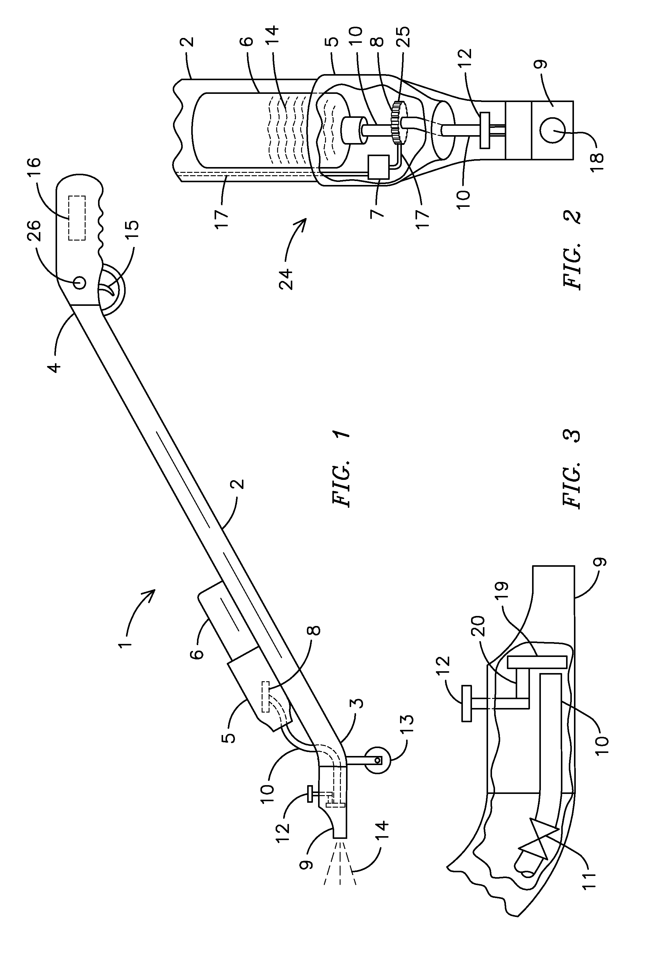
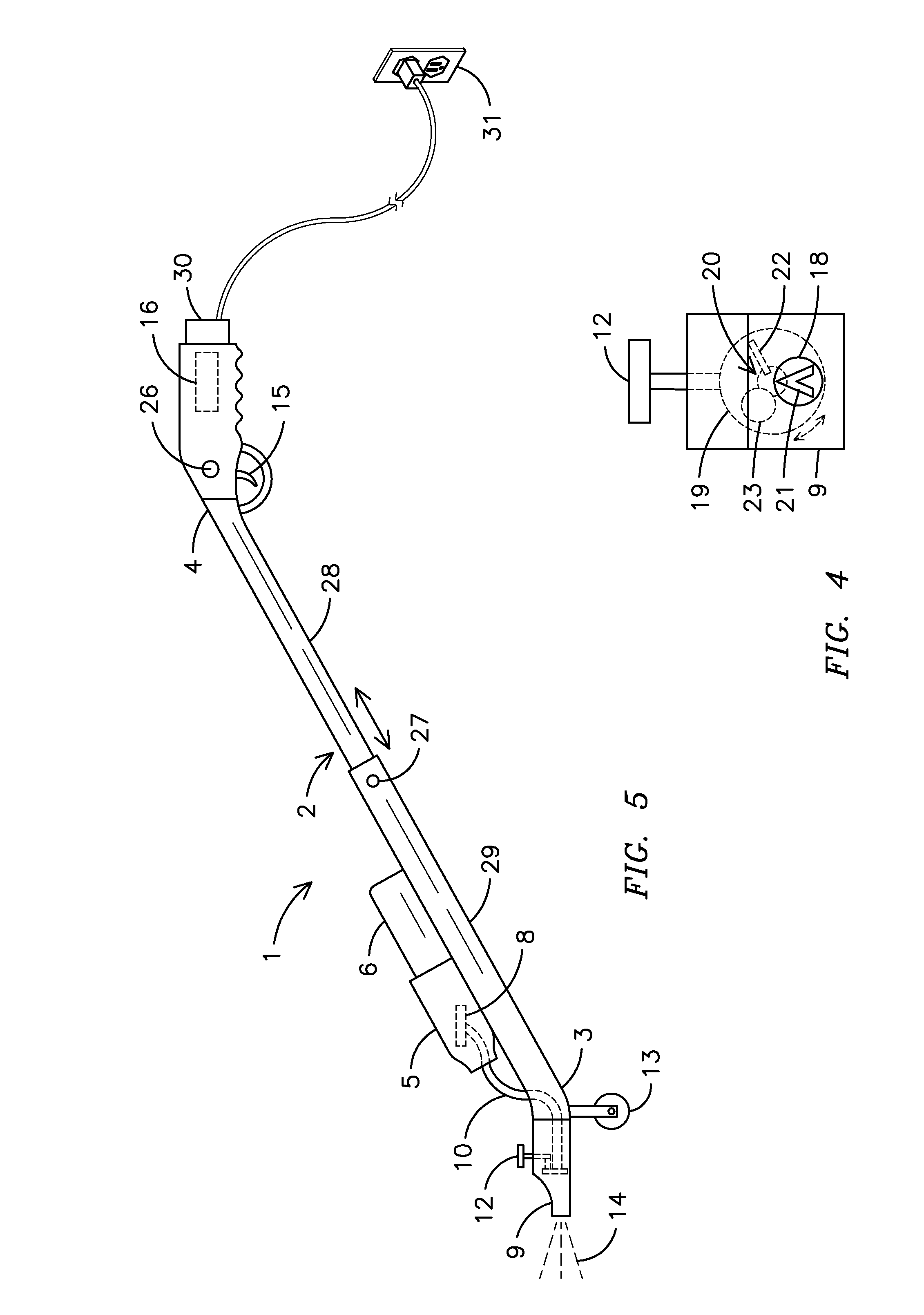
[0022]For purposes of describing the preferred embodiment, the terminology used in reference to the numbered components in the drawings is as follows:[0023]1. liquid dispensing device, generally[0024]2. handle[0025]3. handle distal end[0026]4. handle proximal end[0027]5. bottle retaining housing[0028]6. bottle[0029]7. electric motor[0030]8. pump[0031]9. spray nozzle[0032]10. conduit[0033]11. valve[0034]12. spray pattern adjustment control[0035]13. wheel[0036]14. liquid[0037]15. trigger[0038]16. battery compartment housing[0039]17. electrical connection[0040]18. aperture[0041]19. adjustment disk[0042]20. adjustment means[0043]21. V-shaped pattern[0044]22. linear-shaped pattern[0045]23. circular-shaped pattern[0046]24. liquid delivery means[0047]25. gears[0048]26. safety button[0049]27. length adjustment button[0050]28. inner handle[0051]29. outer handle[0052]30. AC adapter[0053]31. electrical receptacle

[0054]With respect to FIG. 1, a side view of a liquid dispensing device of the pre...


PUM


Abstract

A liquid dispensing device (1) having an elongated handle (2) with a distal end (3) and a proximal end (4), a bottle retaining housing (5) located on the handle (2) for the acceptance of a liquid-filled bottle (6), an electric motor (7), a trigger (15) in electrical connection with the motor (7), a pump (15) located within the bottle retaining housing (5) and in electrical connection with the electric motor (7) wherein the pump (8) is in fluid connection with the liquid (14), a spray nozzle (9) in fluid connection with the pump (8) via a conduit (10), an open and closeable valve (11), a spray pattern adjustment control (12) located proximate to the spray nozzle (9), a spray pattern adjustment control (12) and a removable wheel (13) located on the distal end (3) of the handle (2). The liquid dispensing device is operational when an electrical current is supplied to the motor (7) to create a predetermined amount of pressure to open the valve (11) and permit a predetermined amount of liquid (14) to flow from the bottle (6) and exit through the nozzle (9).

Description

BACKGROUND OF THE INVENTION[0001]This invention relates to liquid dispensing devices, more particularly, a liquid dispensing device that permits a user to quickly and easily dispense a liquid onto a surface.[0002]Currently, many individuals use hand-held pump reservoir systems to spray liquid fertilizer and / or pesticides on a lawn. The user adds a predetermined amount of liquid to the reservoir, secures a cap thereon, pressurizes the reservoir and sprays the liquid onto the lawn. However, many individuals find the use of such reservoirs difficult as the user must carry the reservoir over the entire area to be sprayed and must repeatedly pump the reservoir to provide a predetermined amount of pressure to spray the liquid. Moreover, because the reservoir is filled with liquid, the user tires easily due to the weight he / she must carry while spraying the lawn. In addition, the entire system is cumbersome to carry due to the bulk of the reservoir.[0003]Moreover, many individuals utilize ...

Claims


Application Information

Patent Timeline
IPC IPC(8): B67D5/01B67D7/00
CPCA01C23/047A01M21/043B05B1/1645B05B1/169B05B9/007B05B9/0416B05B9/0861
Inventor REELICK, EUGENE A.
Owner REELICK EUGENE A
Why Eureka
Try Eureka