Power conditioner and method of managing the same

Inactive Publication Date: 2008-10-23
SAMSUNG ELECTRONICS CO LTD
View PDF7 Cites 7 Cited by
  • Summary
  • Abstract
  • Description
  • Claims
  • Application Information

AI Technical Summary

Benefits of technology

[0009]To solve the above and/or other problems, aspects of the invention relate to a power conditioner that pr

Problems solved by technology

However, in the power conditioner described above, power to be supplied to the BOP elements 70 must pass through the main converter 20 and the auxiliary converter 60, resulting in an inevitable power loss due to the two voltage conversions that are performed.
Power loss o

Method used


Image

  • Power conditioner and method of managing the same
  • Power conditioner and method of managing the same
  • Power conditioner and method of managing the same

Examples


Example

[0026]Reference will now be made in detail to embodiments of the invention, examples of which are shown in the accompanying drawings, wherein like reference numerals refer to like elements throughout. The embodiments are described below in order to explain the invention by referring to the figures.

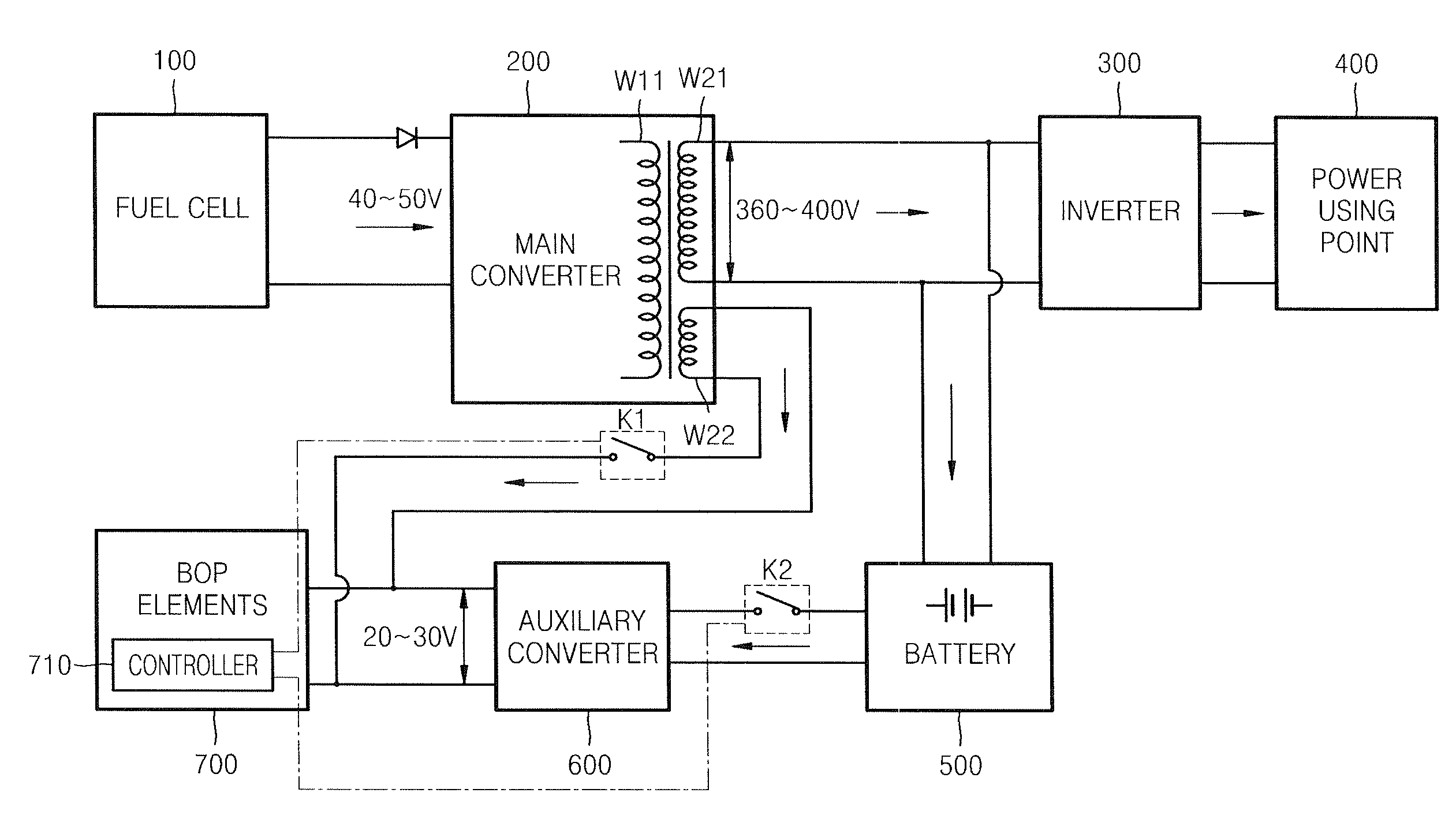
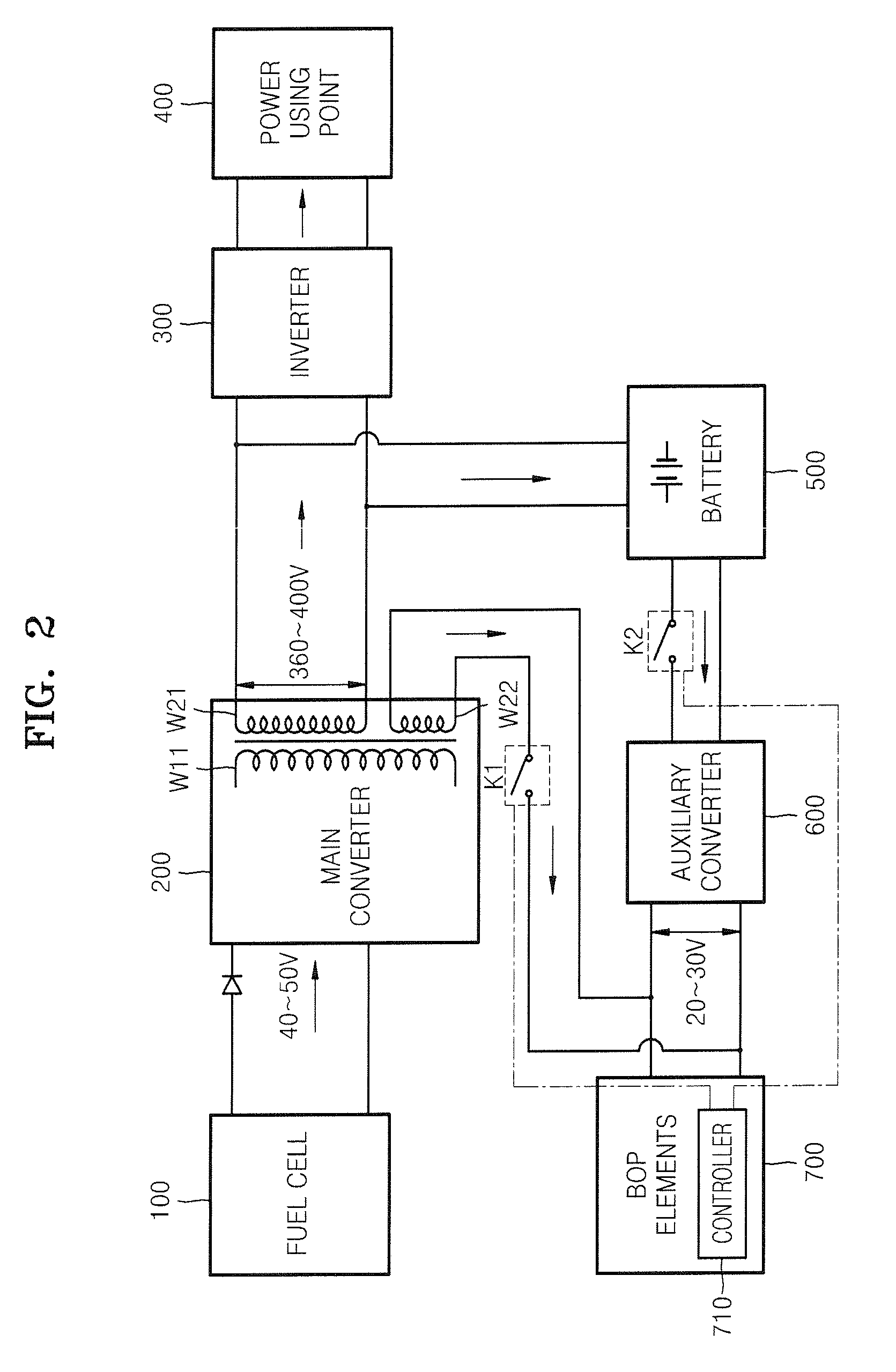
[0027]FIG. 2 is a block diagram of a power conditioner according to an aspect of the invention.

[0028]Referring to FIG. 2, a power conditioner according to an aspect of the invention has a basic configuration in which, after a DC voltage outputted from a power source, such as a stack of a fuel cell 100, is boosted in a main converter 200, the boosted DC voltage is supplied to a power using point 400 by converting the boosted DC voltage into an AC voltage in an inverter 300, and the boosted DC voltage outputted from the main converter 200 is reduced to a predetermined DC voltage and is supplied to BOP elements 700. Reference numeral 710 indicates a controller that controls the main converter...


PUM


Abstract

A power conditioner includes a main converter to transform a voltage outputted from a power source into a first transformed voltage and output the first transformed voltage to supply power to a power using point; and an auxiliary converter to transform the first transformed voltage outputted from the main converter into a second transformed voltage and output the second transformed voltage to supply power to balance-of-plant (BOP) elements including driving devices of the power source. The main converter includes a first winding to transform the voltage outputted from the power source into the first transformed voltage and output the first transformed voltage to supply power to the power using point; and a second winding to transform the voltage outputted from the power source into a third transformed voltage and output the third transformed voltage to supply power directly to the BOP elements, thereby bypassing the auxiliary converter.

Description

CROSS-REFERENCE TO RELATED APPLICATIONS[0001]This application claims the benefit of Korean Patent Application No. 2007-37613 filed on Apr. 17, 2007, in the Korean Intellectual Property Office, the disclosure of which is incorporated herein by reference in its entirety.BACKGROUND OF THE INVENTION[0002]1. Field of the Invention[0003]Aspects of the invention relate to a power conditioner for supplying power generated from a fuel cell or a solar cell to a power using point, and a method of managing the power controller.[0004]2. Description of the Related Art[0005]According to the related art, power generated by a fuel cell is supplied to a power using point through a power conditioner, as shown, for example, in FIG. 1. FIG. 1 shows a block diagram of a power conditioner disclosed in U.S. Patent Application Publication No. 2004 / 0219399. Referring to FIG. 1, a direct current (DC) voltage of approximately 40 to 50V generated by a fuel cell 10 constituting a power source is boosted to a DC ...

Claims


Application Information

Patent Timeline
IPC IPC(8): H02J1/00
CPCH01M8/04888H01M8/0494H01M8/04947H01M16/006H02J7/34Y02E60/50Y02E60/10H02J3/38H02J3/46
Inventor WANG, YONGOH, DUK-JINCHOI, SEE-YOUNG
Owner SAMSUNG ELECTRONICS CO LTD
Why Eureka
Try Eureka