System and method for telescope guiding utilizing an artificial reference star

a technology of artificial reference star and telescope, applied in the field of telescopes, can solve the problems of wasting a portion of the ccd area, user must refocus the guide ccd, and long exposure time is required

Inactive Publication Date: 2008-10-23
DIFFRACTION
View PDF4 Cites 6 Cited by
  • Summary
  • Abstract
  • Description
  • Claims
  • Application Information

AI Technical Summary

Benefits of technology

[0013]The artificial reference star is preferably created by generating a point source of light in the vicinity of the imaging means within the main telescope, directing the light from the point source outside of the main telescope via its aperture, and retroreflecting the output beam at the same direction angle of the beam exiting the aperture into the guide scope. This effectively locks the guide scope to the line of sight of the imaging means, and makes it possible to guide the main scope by maintaining the positional displacement between the selected guide star and the artificial star on the guide scope's focal plane approximately constant.
[0014]The wavelength of the output beam is preferably outside the spectral passband of the imaging means, which is typically a CCD array. If needed, filters can be placed between the point source of light and the imaging means to limit the amount of point source light that impinges on the imaging means.

Problems solved by technology

In some cases, particularly when the object is dim, a long exposure time is required to gather enough light to form a useful image.
This technique generally works well, but suffers from several problems.
Another problem is that, at longer focal lengths and larger F / numbers, good guide stars are relatively uncommon, forcing a user to either offset his imaging CCD from the object being imaged to find a guide star, or to rotate the whole assembly to find a guide star.
Both are detrimental to astrophotography, since the imaging CCD is expensive in large sizes, and it is frustrating to have to lose the proper framing of a scene to find a guide star, effectively wasting a portion of the CCD area.
However, with this arrangement, the guide CCD still only views a small area of sky, and requires offsetting or rotating the main CCD to find a guide star.
Another problem in practice is that, if filters are used with different thicknesses, the user must refocus the guide CCD when changing filters.
However, the problem with this approach is that any mechanical deflection of the guide scope relative to the main scope will cause guiding errors, resulting in elongated stars and ruining the image.
A guiding error of as little as one arc-second—which is a mechanical displacement of only 60 micro-inches across a 12 inch baseline, typical of guide scope support clamp spacing—can be deleterious.
Most telescope mounts are massive, supporting hundreds of pounds of telescopes and counterweights, and have difficulty making fast, accurate correction of the star image position on the imaging CCD.
However, this arrangement is not possible when a separate guide scope is used, since the guide CCD does not view the sky through the AO device.
Thus, the solution that makes finding guide stars easiest cannot be used to control an AO device in the closed loop manner that is required for accurate guiding.

Method used


Image

  • System and method for telescope guiding utilizing an artificial reference star
  • System and method for telescope guiding utilizing an artificial reference star
  • System and method for telescope guiding utilizing an artificial reference star

Examples


Embodiment Construction

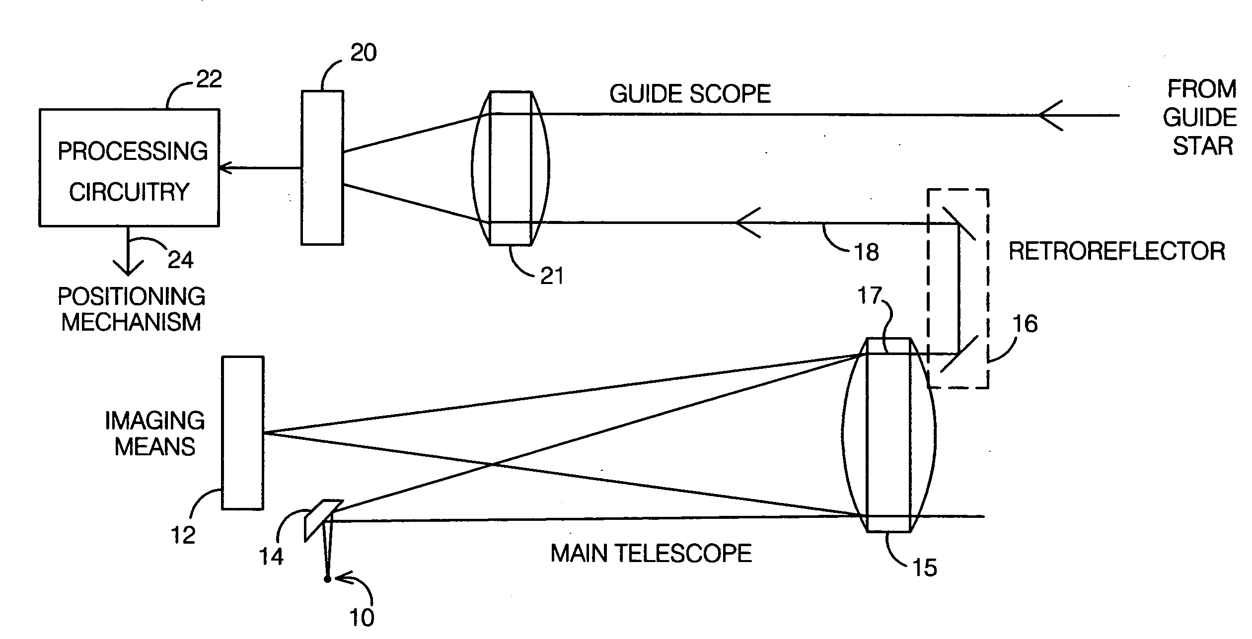
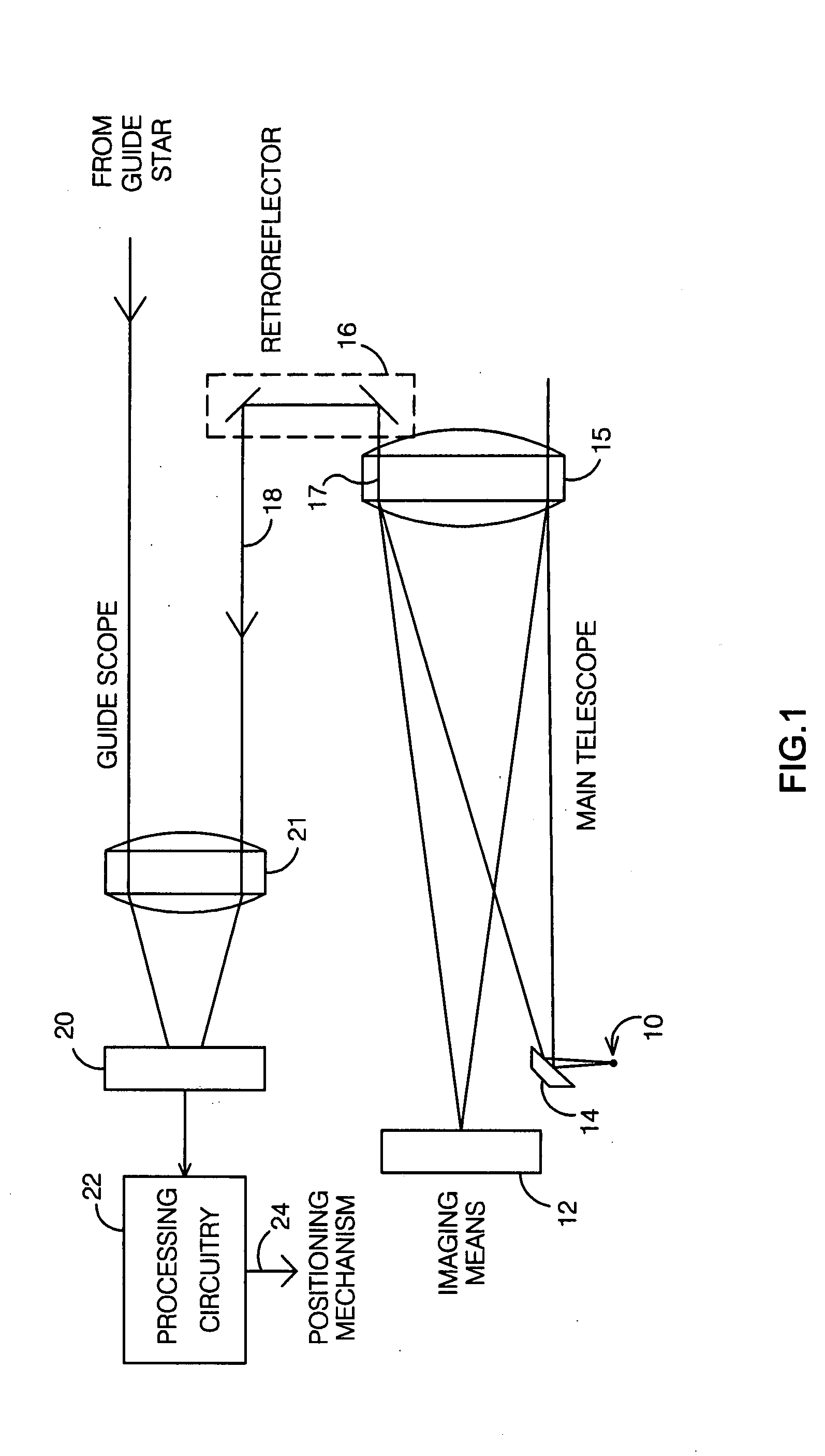
[0023]The new method of guiding an optical device is described. The method is applicable whenever there is a guide means which facilitates the proper positioning of a main imaging means. A primary application is a telescope system having a main scope, the positioning of which is facilitated with the use of a guide scope.

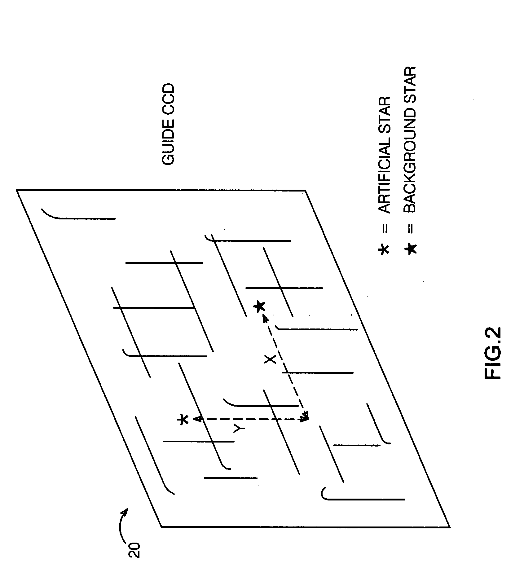
[0024]The method involves creating an artificial reference star in the FOV of a guide scope which is locked to the line of sight of the imaging means of the main scope. A real guide star is selected which is within the FOV of the guide scope; the guide scope has an associated focal plane on which both artificial and real guide stars are focused. Guiding of the main scope is effected by maintaining its line of sight such that the positional displacement between the selected real guide star and the artificial star on the guide scope's focal plane is maintained approximately constant.

[0025]One possible embodiment of a guide means per the present invention is shown in FI...


PUM


Abstract

A system and method for telescope guiding requires creating an artificial reference star which is locked to the line of sight of the imaging means of a main telescope in the field-of-view (FOV) of a guide scope. A real guide star is selected using the guide scope, such that both artificial and guide stars are within the FOV of the guide scope. Guiding is accomplished by varying the line of sight such that the positional displacement between the guide and artificial stars on the guide star's focal plane is maintained approximately constant. The artificial star is created by generating a point source of light near the main scope's imaging means, directing the light outside the main scope and retroreflecting it at the same direction angle of the beam exiting the aperture into the guide scope, effectively locking the guide scope to the line of sight of the imaging means.

Description

BACKGROUND OF THE INVENTION[0001]1. Field of the Invention[0002]This invention relates generally to the field of telescopes, and more particularly to systems and methods for telescope guiding.[0003]2. Description of the Related Art[0004]Images of celestial objects are typically captured using a telescope, to which an imaging device such as the charge-coupled device (CCD) array of a camera has been coupled. In some cases, particularly when the object is dim, a long exposure time is required to gather enough light to form a useful image. When this is the case, it is necessary to adjust or “guide” the position of the telescope during the exposure, to ensure that the object remains accurately positioned on the imaging device. “Clock drives” which compensate for the earth's rotation are commonly employed; however, occasional correction is typically required to maintain a desired accuracy.[0005]Many techniques have been employed to provide the necessary guiding. One common method involves...

Claims


Application Information

Patent Timeline
Patent Type & Authority Applications(United States)
IPC IPC(8): G02B23/00
CPCG01B11/27G02B23/14G02B23/10
Inventor HOLMES, ALAN W.
Owner DIFFRACTION
Why Eureka
Try Eureka