

Multipotential Expanded Mesenchymal Precursor Cell Progeny (Memp) and Uses Thereof
a mesenchymal precursor and multi-potential expansion technology, applied in the field of mesenchymal precursor cell progeny (memps), can solve the problems of reducing the number of mesenchymal precursor cells
- Summary
- Abstract
- Description
- Claims
- Application Information
AI Technical Summary
Benefits of technology
Problems solved by technology
Method used
Image

Examples
example 1
Stro-1dim Cultured Cells are More Committed While Stro-1bri Cells are Less Committed Precursor Cells
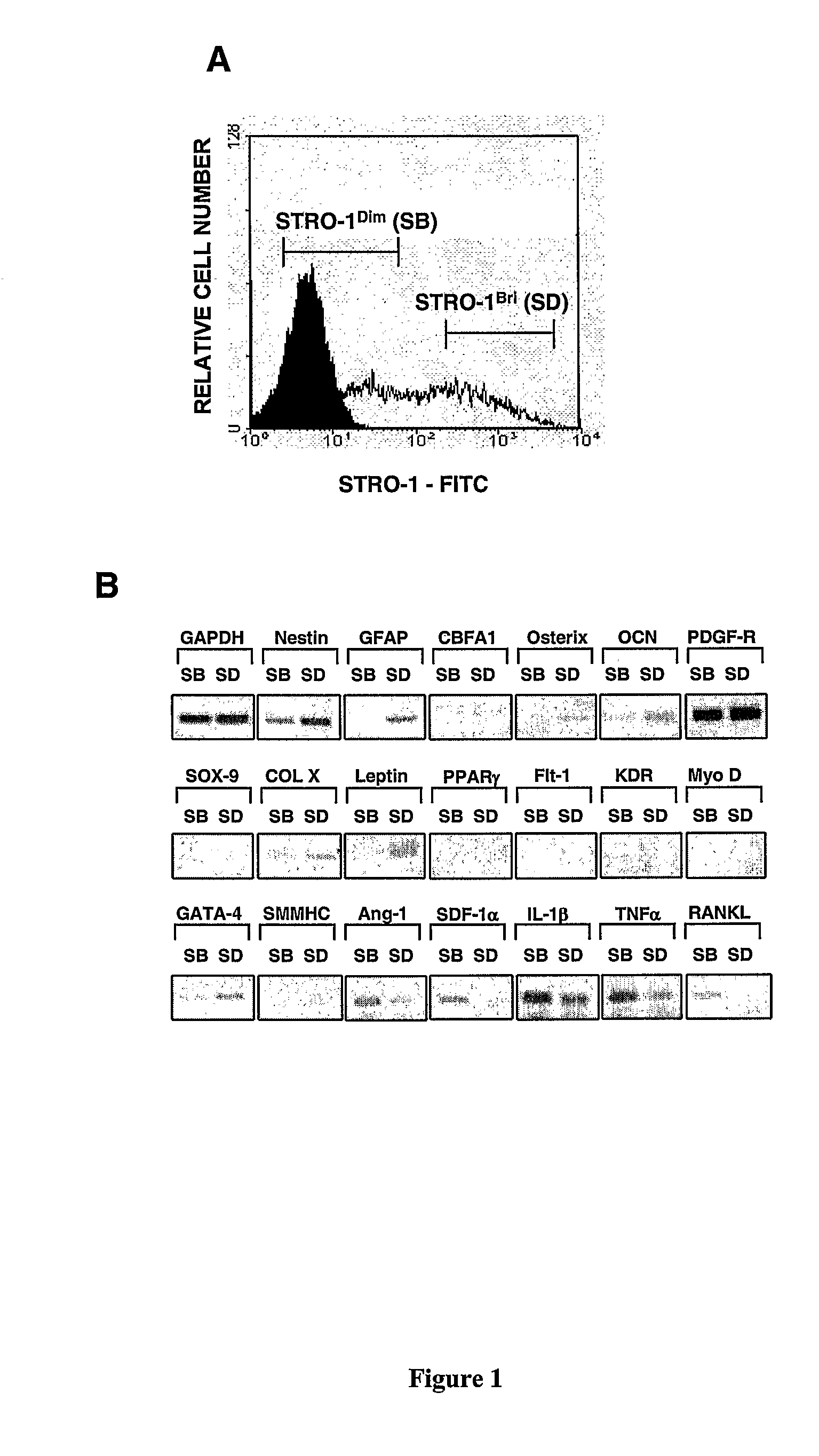
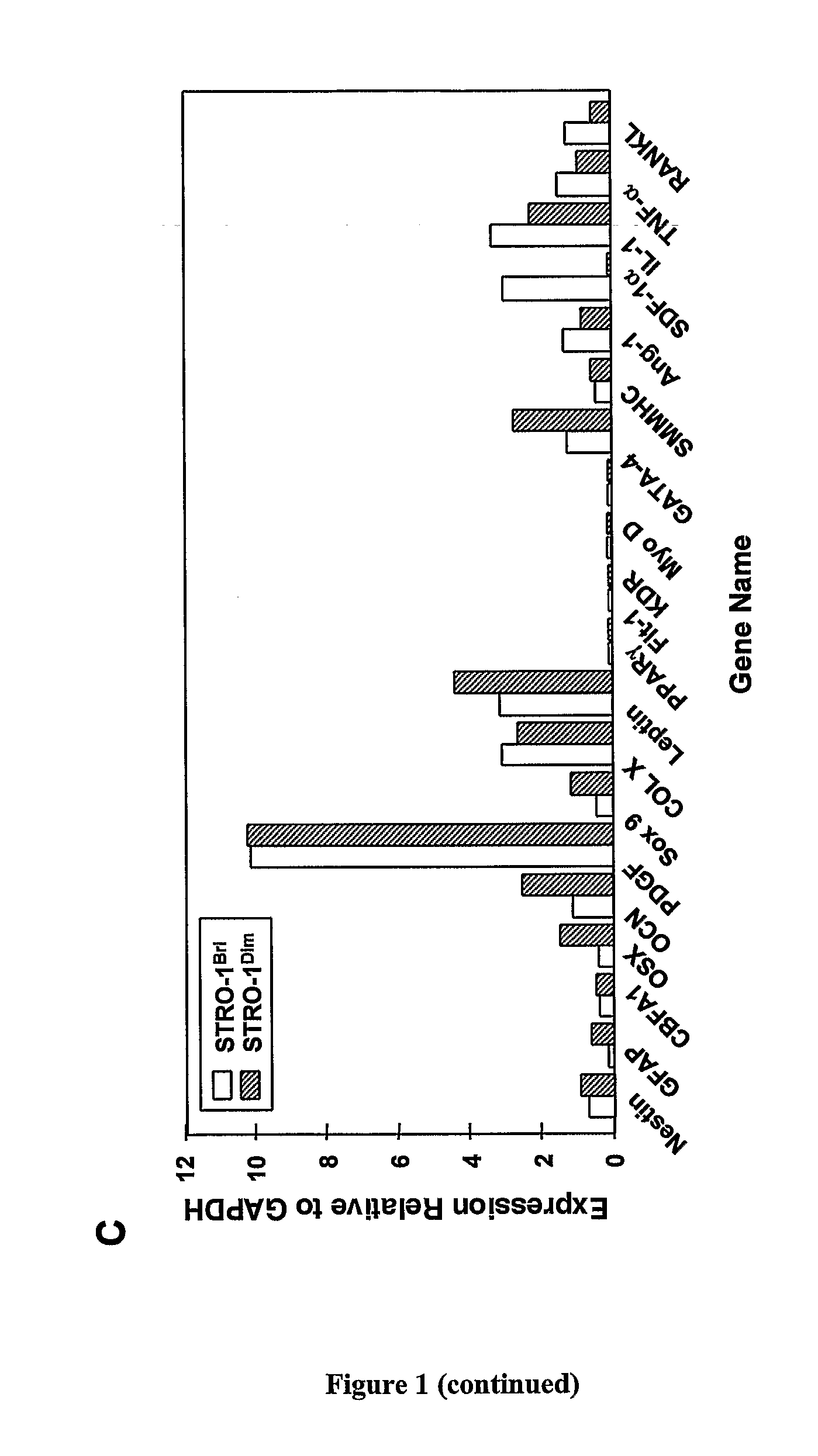
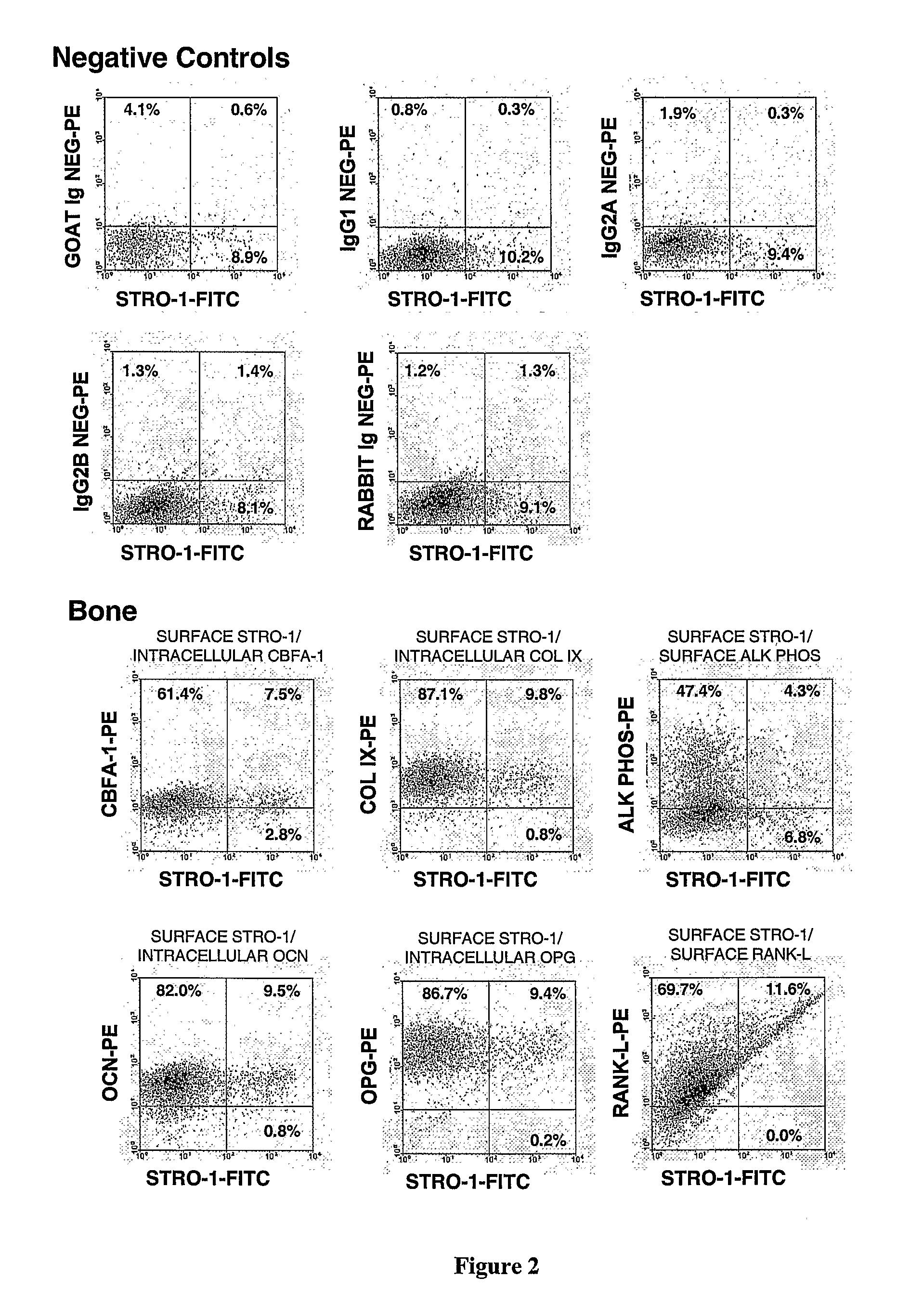
[0225]We have previously reported that multipotential mesenchymal precursor cells (MPC) can be purified from adult human bone marrow mononuclear cells based on the phenotype STRO-1bri / VCAM-1 (CD106)+ or STRO-1bri / MUC-18 (CD146)+(Gronthos et al. J. Cell Sci 116:1827-1835, 2003; Shi and Gronthos J B M R 18(4): 696-704, 2003; PCTAU2004 / 000416). The MPC population can be readily expanded in vitro under defined culture conditions (Gronthos et al. J. Cell Sci 116:1827-1835, 2003). We now present data characterising the ex vivo expanded MPC progeny based on markers associated with different cell lineages, at both the mRNA and protein level, using reverse transcription-polymerase chain reaction (RT-PCR) and flow cytometric analysis, respectively. Whilst, all freshly isolated bone marrow MPC express STRO-1 at high levels (Stro-1bri), the majority of cells down regulate STRO-1 expression (Stro-...
example 2
Differential Capacity of STRO-1dim and STRO-1bri Cultured Cells (MEMPs) to Differentiate In Vitro
[0226]We next examined whether the observed differences in the gene and protein expression profiles of STRO-1dim and STRO-1bri cultured cells was reflective of any functional differences in their capacity to differentiate into multiple cell lineages. Cultures of ex vivo expanded STRO-1bri / CD146+ derived cells were isolated by FACS based on their expression of STRO-1 antigen as described above. FACS isolated STRO-1dim and STRO-1bri cultured cells were subsequently plated under inductive conditions for fat (FIG. 3), bone (FIG. 4) and cartilage (FIG. 5) formation. In all cases STRO-1 cultured cells showed a higher capacity to form fat, bone and cartilage under the specified conditions when compared with STRO-1dim cultured cells. The data from these experiments, substantiate the gene and protein expression results obtained above, demonstrating that STRO-1bri cultured cells are a primitive po...
example 3
STRO-1bri Cells (MEMPs) can Modify the Growth Potential of Tissue Specific Committed Cells (TSCC) In Vitro and In Vivo
[0227]The identification of the two different ex vivo expanded MPC derived cell populations representative of different developmental stages has significant implications in the use of whole cultured preparations derived from Stro-1bri cells for clinical therapies. Initial studies were design to examine the influence of primitive, less committed STRO-1bri cultured MPC on the growth of more mature and committed STRO-1dim cultured TSCC. Experiments were designed to add increasing percentages of FACS isolated STRO-1bri cultured MPC with FACS isolated STRO-1dim cultured TSCC, previously labelled with a fluorescent tag, CFSE. FIG. 6 shows that the proliferation of labelled STRO-1dim cells is effected by the presence of unlabelled STRO-1bri cells. When a CFSE labelled cell divides the two daughter cells contain half the fluorescence of the parental cell. Therefore, differen...
PUM
| Property | Measurement | Unit |
|---|---|---|
| Fraction | aaaaa | aaaaa |
| Fraction | aaaaa | aaaaa |
| Fraction | aaaaa | aaaaa |
Abstract
Description
Claims
Application Information