Precision sharpener for hunting and asian knives

a technology for asian knives and sharpeners, which is applied in the field of precision sharpeners for hunting and asian knives, can solve the problems of serious compromise of the precise angular control of the facets being ground at the knife edge, and the limited precision of hunting style knives and certain asian knives in knife sharpeners

Active Publication Date: 2008-10-23
EDGECRAFT
View PDF31 Cites 31 Cited by
  • Summary
  • Abstract
  • Description
  • Claims
  • Application Information

AI Technical Summary

Benefits of technology

[0004]An object of this invention is to provide a sharpener capable of precision sharpening hunting style knives and various Asian knives.

Problems solved by technology

Precision sharpening of hunting style knives and certain Asian knives in knife sharpeners has historically been limited because of imprecise control of the angle of the blade's cutting edge facet as presented to the moving abrasive.
Because of the complex geometric design of the face of hunting and certain Asian knife blades the positioning of these style blades on such angle guides is unstable and ambiguous, consequently precise angular control of the facets being ground at the knife edge is seriously compromised.

Method used


Image

  • Precision sharpener for hunting and asian knives
  • Precision sharpener for hunting and asian knives
  • Precision sharpener for hunting and asian knives

Examples


Embodiment Construction

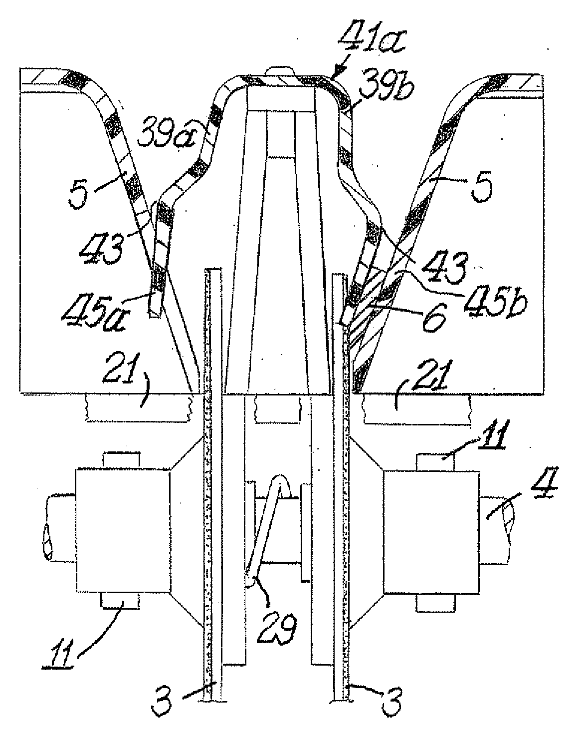
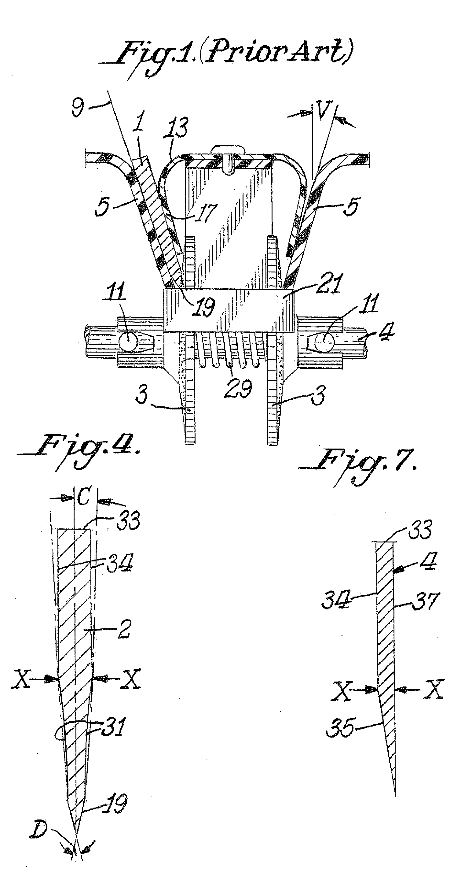
[0015]FIG. 1 illustrates the conventional prior art means of controlling the position of a knife blade 1 as its edge facet is placed into contact with a rotating abrasive-covered disk 3. The abrasive disk mounted on shaft 4 is motor driven. The motor is not shown. The conventional knife blade 1 is positioned by hand against the inside surface plane of the knife guide 5 and is pressed against that surface by a conventional inverted U shaped spring 13 that has a large flat arm 17 that presses against the right flat face of a conventional knife 1. This type of knife holding spring conforms well to the flat face of a conventional knife blade and presses the knife's back face into good alignment with the contacting planar surface of the guide 5. Thus a knife whose faces are planar and parallel is securely positioned between arm 17 of the spring 13 and the contacting flat surface of guide 5.

[0016]Most kitchen knives, pen knives, slicers, and chefs' knives have flat faces and for these kni...


PUM

PropertyMeasurementUnit
angleaaaaaaaaaa
edge angleaaaaaaaaaa
thicknessaaaaaaaaaa

Abstract

A knife sharpener is provided which is capable of precision sharpening of hunting and similar knives that have a first and second blade face, each of which terminates at a facet that meets the corresponding facet to create the knife edge. At least the first of the blade faces has a lower distinct planar or concave section adjacent the edge facet with the lower planar or concave section of the face being set at an angle to the center line of the blade thickness that is different from the angle of the adjoining upper section of the same blade face located adjacent to the back of the blade. The sharpener includes a sharpening member such as one having an abrasive coated surface. The sharpener also includes a planar angle knife guide surface of a knife guide which is designed for intimate sliding and sustaining contact with the second face of the blade in order to position an edge facet on the first of the faces into precise angular relation with the sharpening surface. The sharpener also includes a knife holding spring that applies force against the first face of the blade predominantly at one or more locations on the lower planar or concave section of the first face that is adjacent to the edge facet being sharpened in order that the lower section adjacent the edge on the second face of the blade is pressured to align with and remain in intimate sliding alignment with the guide surface as the blade edge facet on the first face is being sharpened.

Description

CROSS-REFERENCE TO RELATED APPLICATION [0001]This application is based upon provisional application Ser. No. 60 / 912,438 filed Apr. 18, 2007, all of the details of which are incorporated herein by reference thereto.BACKGROUND OF THE INVENTION [0002]Precision sharpening of hunting style knives and certain Asian knives in knife sharpeners has historically been limited because of imprecise control of the angle of the blade's cutting edge facet as presented to the moving abrasive.[0003]Commonly in sharpeners to control the sharpening angle, the face of the hunting knife is laid on a planar angle guide surface and held there by hand, by a magnet or a spring. Because of the complex geometric design of the face of hunting and certain Asian knife blades the positioning of these style blades on such angle guides is unstable and ambiguous, consequently precise angular control of the facets being ground at the knife edge is seriously compromised.SUMMARY OF INVENTION [0004]An object of this inve...

Claims


Application Information

Patent Timeline
Patent Type & Authority Applications(United States)
IPC IPC(8): B24B3/40B24B3/36
CPCB24B3/54
Inventor FRIEL, DANIEL D.ELEK, BELA
Owner EDGECRAFT
Why Eureka
Try Eureka