Apparatus and method of separating a polymer from a solvent

a technology of solvent and apparatus, applied in the field of apparatus and method of separating a polymer from a solvent, can solve the problems of high heat, extended compounding and extruding time, and high shear ra

Inactive Publication Date: 2008-10-23
SABIC INNOVATIVE PLASTICS IP BV
View PDF21 Cites 17 Cited by
  • Summary
  • Abstract
  • Description
  • Claims
  • Application Information

AI Technical Summary

Problems solved by technology

To prepare a polymer product having uniformly dispersed filler or to uniformly disperse an additional polymer, high shear rates, extended compounding and extruding times, and high heat may be required.
The long residence times of compounding and high heat render the polymer product susceptible to discoloration and degradation of desired physical properties.

Method used


Image

  • Apparatus and method of separating a polymer from a solvent
  • Apparatus and method of separating a polymer from a solvent
  • Apparatus and method of separating a polymer from a solvent

Examples


examples 1 through 6

[0110]Equipment, Materials and Procedures:

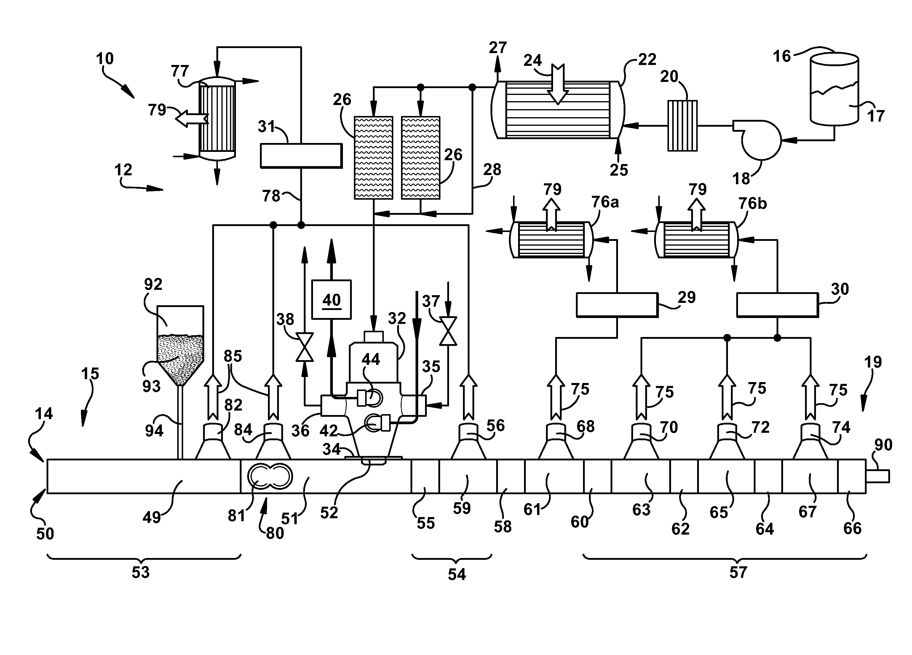
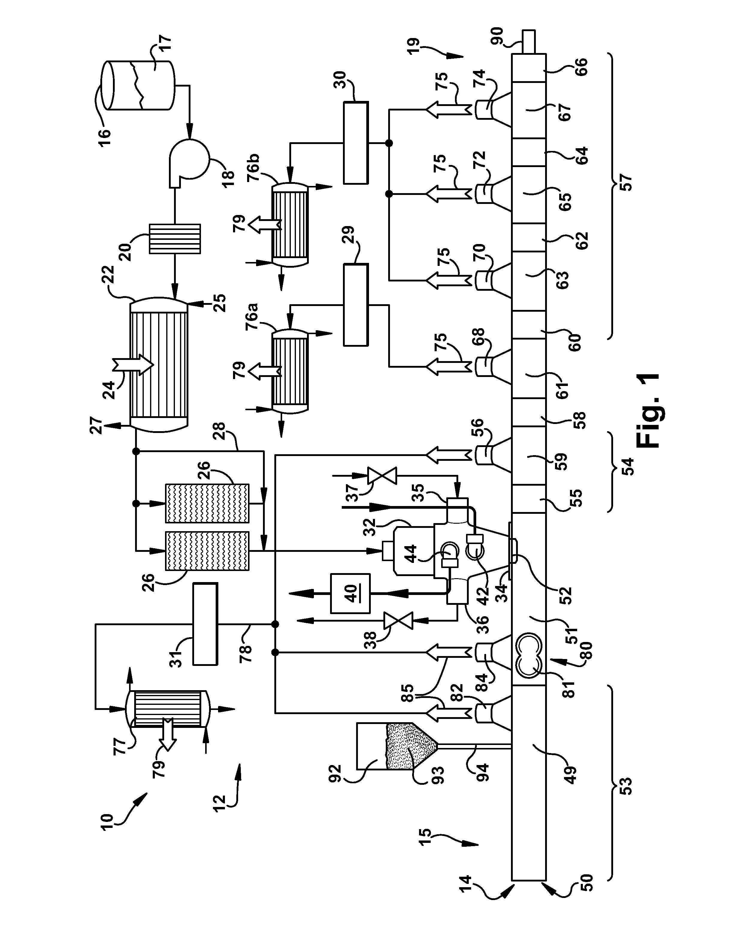
[0111]A laboratory scale extruder similar to the arrangement as shown in FIGS. 2 and 9 was used to separate an Ultem polymer from dilute solutions of the polymer in a solvent or a mixture of solvents. This process included a 25 mm-diameter, co-rotating intermeshing twin-screw extruder, that contained ten barrels (extruder length-to-diameter ratio equal to 40 The extruder apparatus included six vents, three of which were operated at atmospheric pressure or slight vacuum, and the remaining three vents were operated at different levels of vacuum. A heat exchanger, and pressure-controlled valve were used upstream of the extruder to produce a, super-heated Ultem / solvent solution that can be fed continuously to the extruder. The two screws used in the extruder include kneading blocks of different design, and a series of double-flighted, conveying screw elements to transport the melt forward and to also accommodate the solvent vapors produced by th...

examples 7 through 10

[0118]Equipment, Materials and Procedure

[0119]In the following Examples and Comparative Example, the effect of design features of the extrusion apparatus on the polymer isolation process was evaluated in terms of heat balance of the process and also the residual solvent and retention of molecular weight in the final product.

[0120]In Examples 7-9 an extrusion apparatus of the arrangement shown in FIG. 9 was used and in Example 10 (Comparative) an extrusion apparatus of the design shown in FIG. 10 was used to carry out the polymer isolation process. In all of the Examples described herein, the polyetherimide of the polyetherimide-solvent solutions. is used with ULTEM® XH polyetherimide which is commercially available from SABIC Innovative Plastics, Mt Vernon, Ind.

[0121]The polymer isolation process of all Examples were carried out practicing the following procedure. A superheated polymer-solvent mixture was introduced into extruder apparatus 14, and the polymer product that resulted w...

example 7

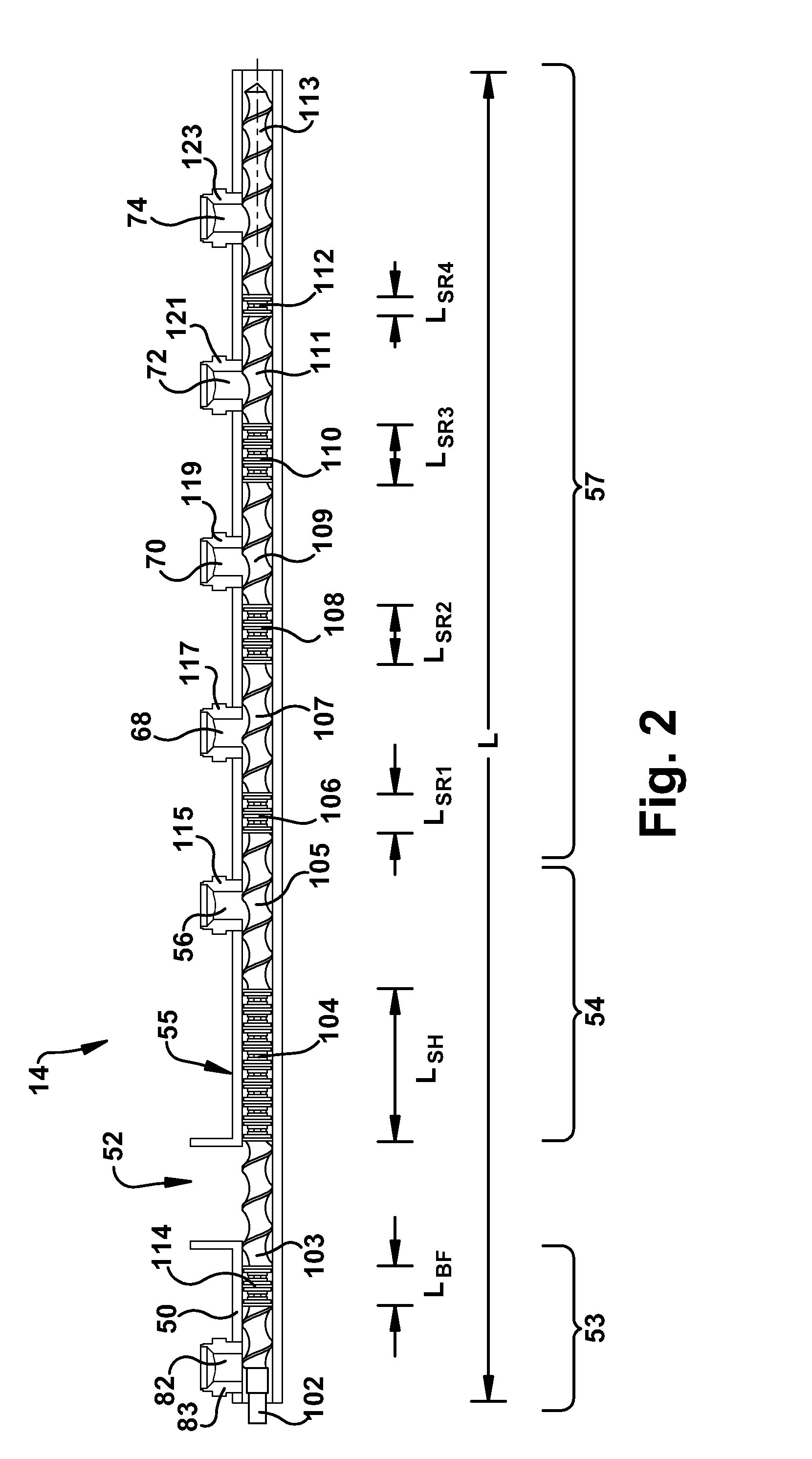
[0123]The polymer isolation process of Example 7 was carried out using an extrusion apparatus as shown in FIG. 9. The extrusion apparatus 14 included a hollow member 50 having a feed port, an upstream portion 53 and a downstream portion 54. The hollow member 50 contained a co-rotating, intermeshing (i.e. self wiping) twin-screws screws having a diameter, D, 58 millimeters and extending from the upstream portion 53 to the downstream portion 54. The internal superheating section 55 was disposed between the feed port 52 and the forward flash vent opening 56. The hollow member had eight (8) vent openings, five downstream vent openings 56, 68, 70, 72 and three upstream vent openings 134, 135, and 136. Four vent openings including the three upstream vent openings 134, 135 and 136 and one downstream vent opening 56, were operated at about atmospheric pressure and the remaining four downstream vent openings 68, 70, 72 and 74 were operated at sub-atmospheric pressure. Vent inserts 115, 117 w...


PUM

PropertyMeasurementUnit
diameteraaaaaaaaaa
boiling pointaaaaaaaaaa
lengthaaaaaaaaaa

Abstract

The present invention relates to various embodiments of a system and method for separating polymer from a solvent. In one embodiment a system for separating polymer from a solvent comprises an extrusion apparatus includes a hollow member having a first end portion, a second end portion, and a feed port between the first end portion and the second end portion. The extrusion apparatus includes a back flash vent port disposed upstream of the feed port and a forward flash vent port disposed downstream of the feed port. The extrusion apparatus further includes a vent insert located at the forward flash vent port, a screw disposed inside the hollow member, and an internal superheating section disposed between the feed port and the downstream vent opening of the hollow member such that the length of the internal superheating section is greater than about four times the diameter, 4D, of the hollow member.

Description

CROSS-REFERENCE TO RELATED APPLICATIONS[0001]This application is a Continuation-in-Part Application of U.S. patent application Ser. No. 11 / 298,365 filed Dec. 8, 2005, which is a Continuation-in-Part Application of U.S. patent application Ser. No. 11 / 144,141 filed Jun. 3, 2005, which is a Continuation Application of U.S. patent application Ser. No. 10 / 648,524, filed Aug. 26, 2003, all of which are incorporated herein in their entirety.BACKGROUND OF THE INVENTION[0002]The preparation of polymeric materials is frequently carried out in a solvent from which the polymer product must be separated prior to molding, storage, or other such applications. This is the case in the manufacture of polyetherimide prepared by condensation polymerization of a dianhydride with a diamine in ortho-dichlorobenzene solution. Many other polymers are similarly prepared in solution and require a solvent removal step in order to isolate the polymer product. Illustrative polymers include interfacially-prepared...

Claims


Application Information

Patent Timeline
Patent Type & Authority Applications(United States)
IPC IPC(8): C08F6/12B29C47/08B29C47/66B29C48/03B29C48/395B29C48/45
CPCB29C47/0009B29C47/0871B29C47/38B29C47/402B29C47/44B29C47/667B29C47/767C08F6/003C08F6/10C08F6/12B29C48/03B29C48/268B29C48/395B29C48/402B29C48/45B29C48/687B29C48/767B29B7/845B29B7/82B29B7/86B29B7/94B29B7/72B29B7/483B29B7/487B29B7/90
Inventor GIAMMATTEI, MARK HOWARDQUEVEDO SANCHEZ, BERNABERAMESH, NARAYANSILVI, NORBERTO
Owner SABIC INNOVATIVE PLASTICS IP BV
Why Eureka
Try Eureka