
Early Detection of Harmful Agents: Method, System and Kit

a technology of harmful agents and detection methods, applied in the field of early detection of harmful agents, can solve the problems of large time delay, and spread of damage caused by harmful agent attack

Inactive Publication Date: 2008-10-23
RAMOT AT TEL AVIV UNIV LTD +1
View PDF2 Cites 92 Cited by
  • Summary
  • Abstract
  • Description
  • Claims
  • Application Information

AI Technical Summary

Benefits of technology

[0213]According to still further features in the described preferred embodiments the detector is capable of providing the image substantially in real time.

Problems solved by technology

Typically, a large time delay occurs between the occurrence of a harmful agent incident, and the time at which the appropriate authorities are able to conclude that a threat is underway.
This diversity of options makes the propagation patterns of harmful agents almost unpredictable.
Unlike conventional bombs, for which the range of damage is limited even if an explosion occurs in a heavily populated location, the damage caused by harmful agent attack can spread, grow with time and cover huge, and in extreme cases, almost unlimited areas.
An utmost pressing problem involving spread of harmful agents is that of early detection and warning.
Such monitoring devices can only alert when a harmful agent incident occurs in the medium in which they are installed.
Threat scenarios, however, are unpredictable in nature and incidents may occur simultaneously in more than one place and / or more than one medium.
In particular, such monitoring devices are practically useless for alerting of a silent or even explosive release of a harmful agent in an open environment.
The built-in fixed sensors, which are generally limited to sensing one area of the building, may be too expensive to be placed in all desired areas of the building.
Other facilities, such as hotels, department stores, shopping malls and the like, are more susceptible to harmful agents, lacking even the aforementioned fixed sensors.
However, because the technological and financial problems associated with adaptation of known techniques a global scale, the harmful agent detection solutions provided by prior art are far from being satisfactory.
Yet, there remain problems in detecting and measuring low levels of compounds conveniently, safely and quickly.
Heretofore, attempt to developed microfluidic devices for the purpose of detecting chemical or biological agents, resulted in only partial success.
Purified enzymes are, however, expensive and unstable, thus limiting their applications in the field of biosensors.
Note, the major drawback of such an approach is the need to maintain at least two cultures of microorganisms on a single sensor which may prove problematic such as due to different nutritional needs.
The above technologies suffer from many limitations.
For example, in most prior art systems, the optical setup which is large, bulky and generally unsuitable for field use.
In addition, there is the problem of obtaining a reliable optical signal, in effect compromising maximizing the signal from the detectable material while minimizing the background signal.
Furthermore, in prior art systems which are based on mechanical scan (e.g., moving electrode, moving light ray or moving sample), inaccurate readings may occur due to misalignment of the various components.
With respect to the sensing process, it is difficult to generate transport of the sample in the channels and to distinguish between signals arriving from different locations.

Method used


Image

  • Early Detection of Harmful Agents: Method, System and Kit
  • Early Detection of Harmful Agents: Method, System and Kit
  • Early Detection of Harmful Agents: Method, System and Kit

Examples


example 1

[0496]CMOS Detector

[0497]Reference is now made to FIG. 22a-b exemplifying an electronic diagram of a CMOS detector 200, which can be used as detector 108, according to a preferred embodiment of the present invention. CMOS detector 200 is known in the art and can be purchased, for example, from Fill Factory, Mechelen Belgium.

[0498]CMOS detector 200 comprises a matrix 201 of elementary units 202 referred to herein as pixels 202. FIG. 22b shows one pixel 202, which comprises a capacitor 204 which is pre-charged to a reset bias voltage, a photodiode 206, for discharging capacitor 204 in response to photons absorption and 3 MOS transistors, designated 208a, 208b and 208c, for resetting (transistor 208a), sensing (transistor 208b) and leading (transistor 208c) the signal to column amplifier 210.

[0499]CMOS detector 200 further comprising a left vertical shift register 212 and a right vertical shift register 214. Left register 212 serves a pointer to a row that is pre-charged to reset bias ...

example 2

Determination of Agent Concentration Using the Detected Signals

[0507]Reference is now made to FIGS. 23a-c, which illustrate the radiation emitted by one reaction chamber of system 10.

[0508]FIG. 23a illustrates reaction chamber 12, a plurality of locations 320, where biological cells generating the florescent materials are located, and a slice 322. Reaction chamber 12 has an aperture 326 through which optical signals 106 (not shown, see FIGS. 23b-c) exit. In the following calculations, slice 322 is represented as equivalent light emitter 324, shown in FIG. 23b. Equivalent light emitter 324 is a superposition of the all the light emitter in slice 322 and can be defined, for example, by integration or summation. Also shown is excitation light 100 and optical signal 106 emitted in a plurality of directions.

[0509]FIG. 23c illustrates the spreading of optical signal 106 through aperture 326 of the reaction chamber. The respective numerical aperture for optical signal 106, designated herei...

example 3

Sensitivity Calculation

[0532]As stated, the emission intensity is proportional to the biochemical reaction percentage expressed by the nGFP parameter. In the present example, a sensitivity calculation is performed using a signal uncertainty parameter, which is proportional to the unfiltered excitation intensity detected by the light detector:

Iunc-px=Un2B·Iexc-px·QEexc,  (EQ. 24)

where Iunc-px is the signal uncertainty parameter, Un2B is the ratio between the uncertainty to the background radiation, Iems-px is the unfiltered excitation intensity as detected by the light detector and QEexc is, as stated, the effective quantum efficiency of the detector for excitation light. A tipical value for Un2B is about 0.5.

[0533]The minimal sensitivity is preferably defined such that the sensed optical signal is at least S2Un times stronger that the signal uncertainty, where S2Un is the ratio between the signal to the uncertainty:

Iems-px·QEems≧S2Un·Iunc-px,  (EQ. 25)

where Iems-px is the emission i...


PUM


Abstract

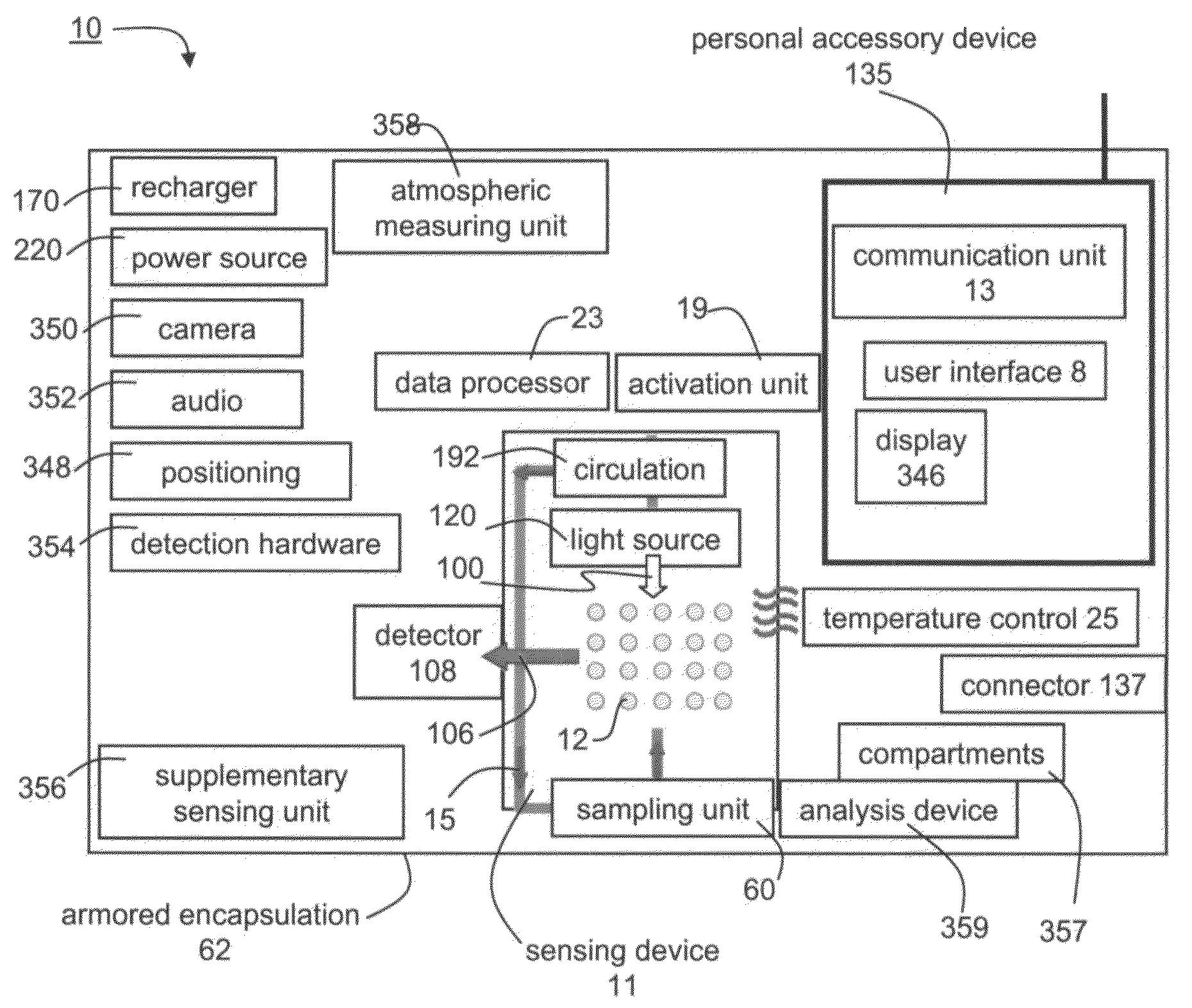
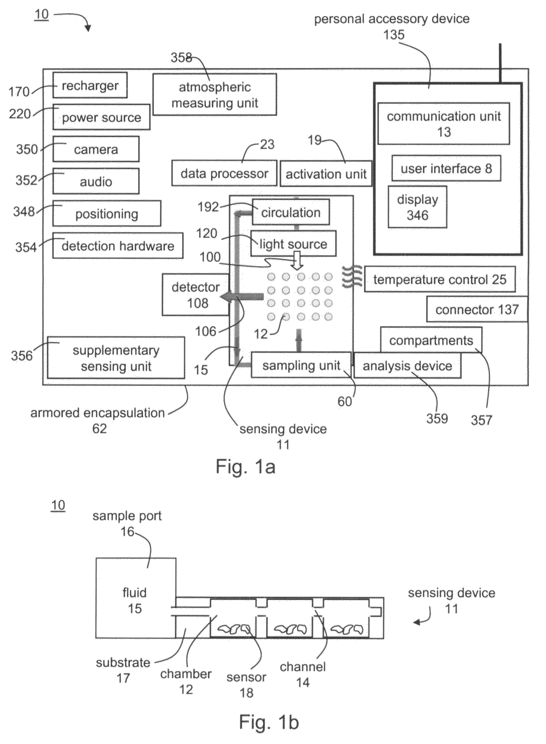
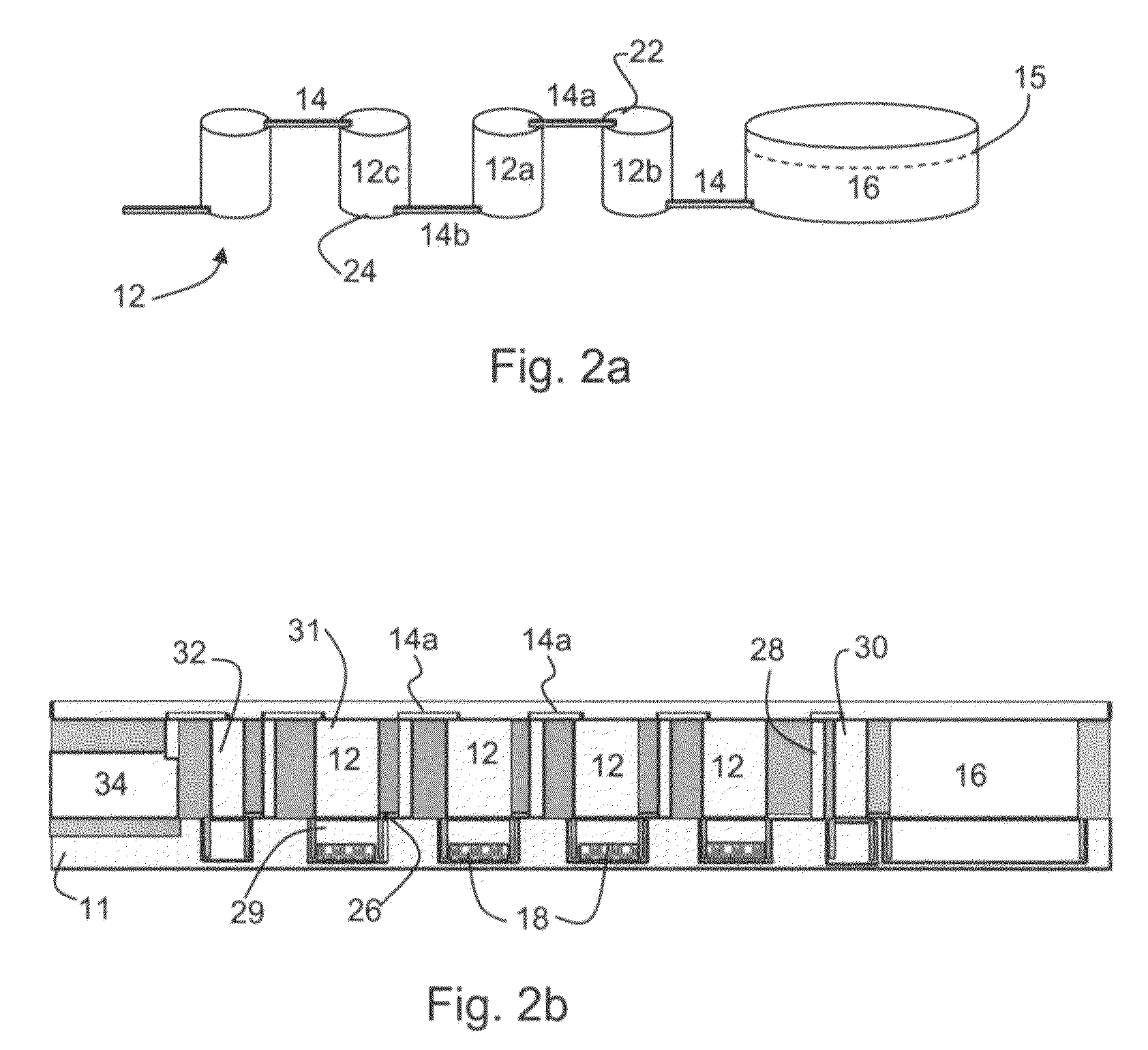
A portable system for detecting agents present in a sample is disclosed. The system comprises a sensing device, having a substrate formed with a plurality of reaction chambers and a plurality of channels interconnecting at least a portion of the plurality of reaction chambers, wherein at least a portion of the plurality of reaction chambers comprises a sensor, capable of generating a detectable signal when exposed to the agents. The system further comprises a detector, which receives signals from the sensing device and provides an image of sensors generating the optical signals. The portable system is connected to a communication network via a communication unit.

Description

FIELD AND BACKGROUND OF THE INVENTION[0001]The present invention relates to harmful agents detection and, more particularly, to early detection and warning of presence or diffusion of harmful agents, such as, but not limited to, chemical, biological or radioactive (CBR) agents.[0002]Spread of harmful agents presents a major concern to the future of mankind. This is due to the non-local nature of the spread whereby the source of such a threat may be relatively localized, but its effect can appear in many other locations.[0003]Typically, a large time delay occurs between the occurrence of a harmful agent incident, and the time at which the appropriate authorities are able to conclude that a threat is underway. For example, when a region, populated by a particular community, becomes contaminated, e.g., by a cargo spill or by a deliberate act of terrorism, a certain period of time lapses before the contamination or the effect thereof is noticed.[0004]The time delay is either due to the ...

Claims


Application Information

Patent Timeline
IPC IPC(8): G01N33/00C12Q1/00A61M5/20B01L3/00G08B21/12A61B5/00G01N21/76C12M1/34
CPCB01L3/5027B01L3/50273B01L7/52B01L2200/10B01L2300/023B01L2300/0654B01L2400/0406B01L2400/0424B01L2400/0457B01L2400/049B01L2400/0683F24F3/16F24F2221/44G01N1/2273G01N21/253G01N21/6454G01N35/00871G01N35/08G01N2001/021G01N2001/022G01N2201/0826G01N2201/0833Y02A90/10
Inventor ERAD, MENDYSHACHAM-DIAMAND, YOSIBELKIN, SHIMSHONRABNER, ARTHURERAD, YARIVPEDAHZUR, RAMIYARMUT, YEHUDA
Owner RAMOT AT TEL AVIV UNIV LTD
Learn More