

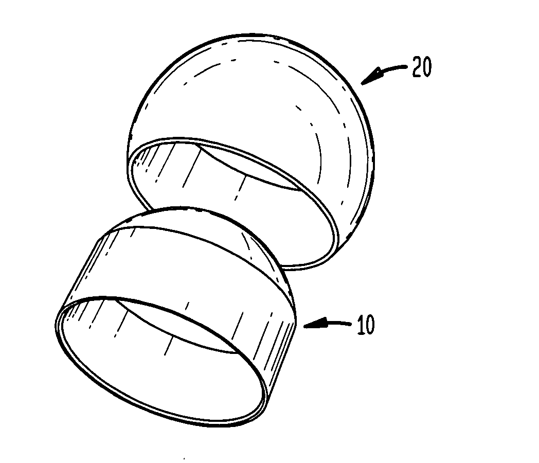
Femoral sleeve for hip resurfacing
a femoral sleeve and hip technology, applied in the field of hip resurfacing femoral sleeves, can solve the problems of adversely affecting the goal of satisfactorily restoring the clinical bio-mechanics of the joint, affecting the performance of these implants, and affecting the ability of the femoral head to be fixed to the bone, so as to facilitate bone ingrowth
- Summary
- Abstract
- Description
- Claims
- Application Information
AI Technical Summary
Benefits of technology
Problems solved by technology
Method used
Image

Examples
Embodiment Construction
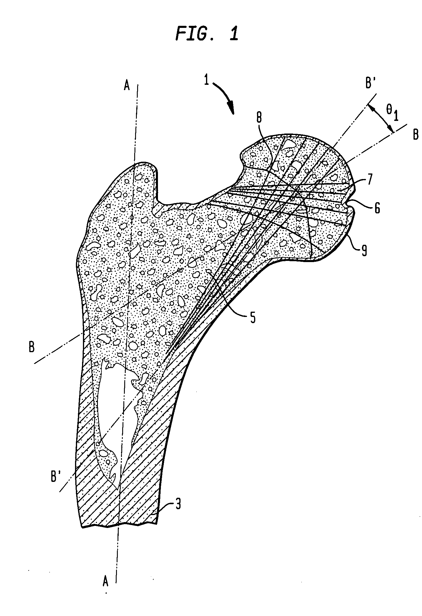
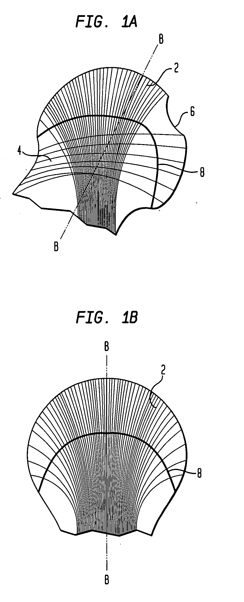
[0054]The location and function of a bone within the body typically define the mechanical properties of that bone. Bone generally comprises dense cortical bone and trabecular or cancelleous bone, which is porous and has an open cancellated structure. Considering the femoral bone of the hip joint, FIG. 1 shows the proximal portion of a femur 1 with the upper portion of the shaft 3, a neck 5 and a head 7. An axis A-A is generally aligned with the shaft 3 and an axis B-B is aligned with the neck 5. The shaft 3 is primarily composed of cortical bone while the neck 5 and head 7 are primarily composed of trabecular bone with cortical bone at the surface. FIGS. 1A and 1B indicate the main groups 2 and 4 of trabeculae in the femoral head 7 in further detail. The group 2 is the principal compressive group through which the resultant load vector at the head due to body weight and muscular force can be shown normally to pass. This group extends from the medial cortex of the femoral shaft 3 to ...
PUM
| Property | Measurement | Unit |
|---|---|---|
| cone angle | aaaaa | aaaaa |
| cone angle | aaaaa | aaaaa |
| porosity | aaaaa | aaaaa |
Abstract
Description
Claims
Application Information