
Tire with reduced rolling noise

a technology of rolling noise and tires, applied in the field of tires, can solve the problems of polluting the environment of vehicles, complex preceding systems, and high cost, and achieve the effect of less noise and positive factors of noise absorption

Inactive Publication Date: 2008-10-30
MICHELIN & CO CIE GEN DES ESTAB MICHELIN
View PDF9 Cites 17 Cited by
  • Summary
  • Abstract
  • Description
  • Claims
  • Application Information

AI Technical Summary

Benefits of technology

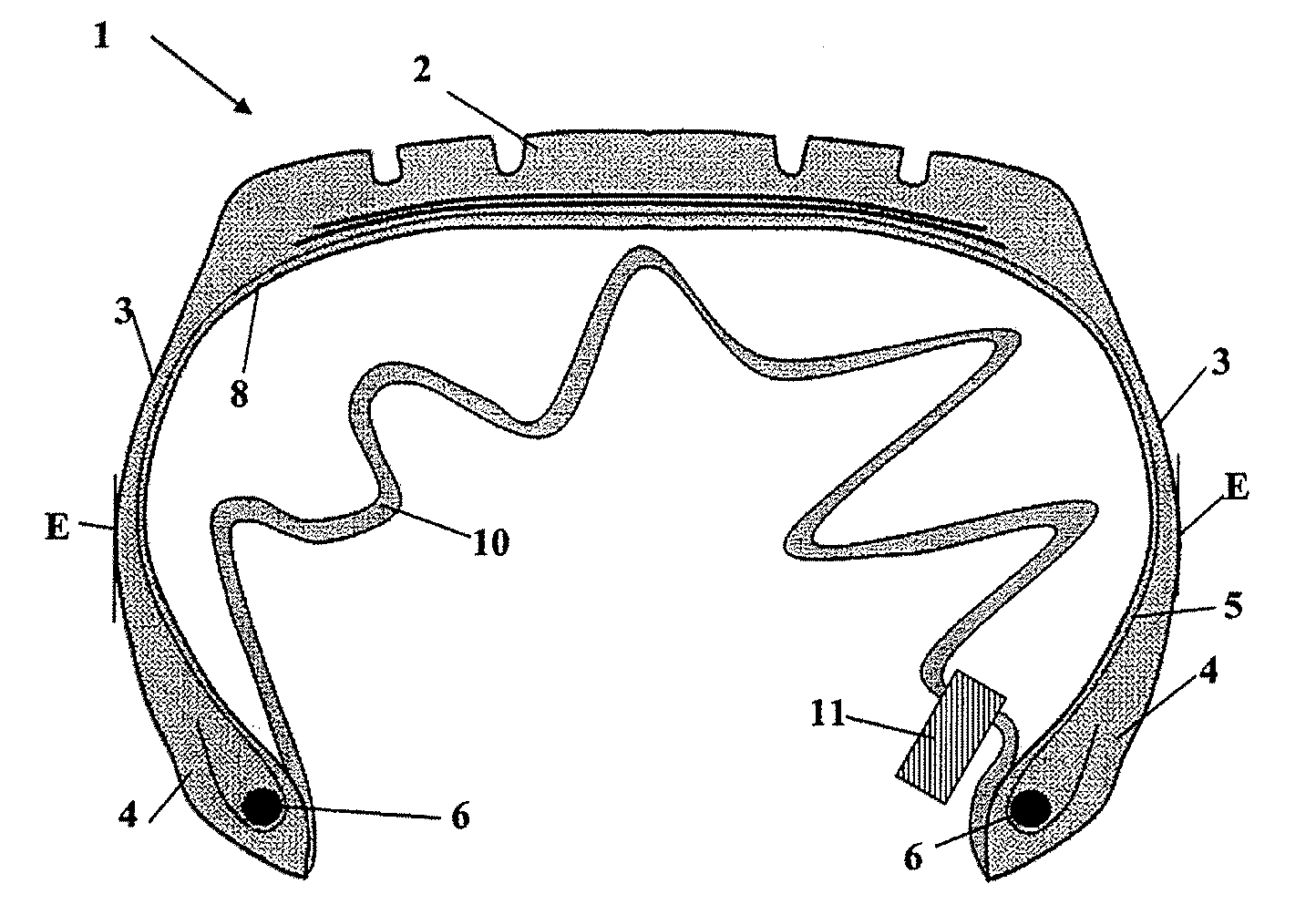
[0015]The fact that the additional layer includes an inflation valve and is bonded to the tire structure at its edges enables the additional layer to be flattened against the rim after the tire is mounted and inflated. The additional layer may thus have a positive effect on damping the rolling noise when the tire is traveling.
[0016]The tire, according to this embodiment of the invention, has the advantage of being able to be mounted onto a non-airtight rim and gives the tire / rim assembly thus formed a behavior very close to that of a conventional tubeless assembly in terms of rolling resistance and puncture resistance.
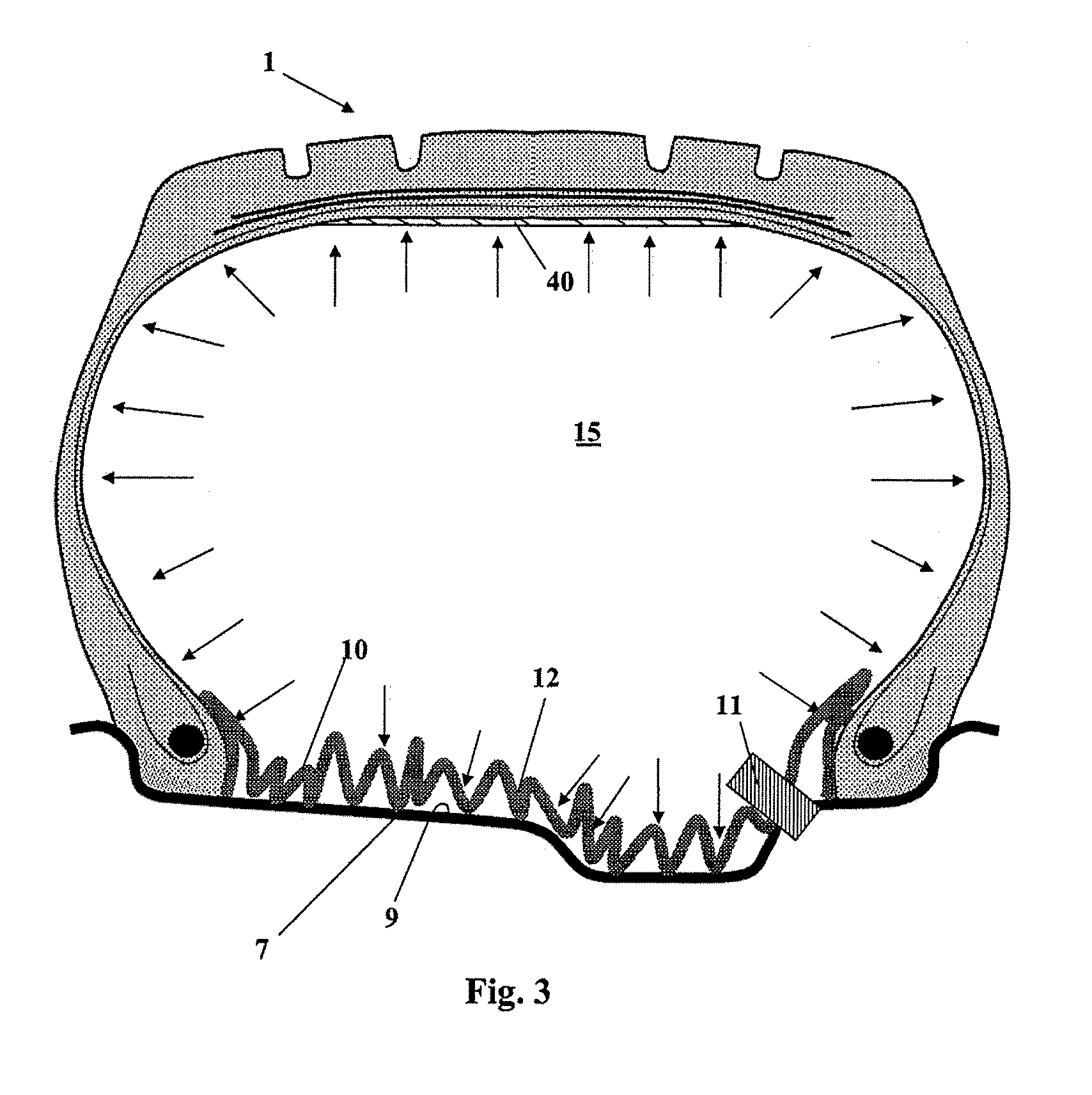
[0018]This guarantees, especially when the additional layer is attached to the inner wall of the tire structure at the beads, that after the tire is on a rim and inflated, the additional layer has an overlength relative to a cross section of the rim and fits against the wall of the rim by forming folds. These folds give an uneven surface that functions to improve the noise absorption capacity when traveling and especially to improve the noise absorption capacity of the first cavity mode.
[0022]The effect on reducing the noise is even more positive when the cellular layer is large compared to the tire, which means that, even after the tire is inflated, the surface of the cellular layer is not taut but is folded. The presence of these folds means that the geometry of the cavity is less “even” and thus the folds are positive factors in noise absorption.
[0029]Advantageously, according to an embodiment, the self-sealing material contains at least one of the constituents chosen from a group that includes glycol, fibers, vulcanized rubber particles, cellular material particles, and mixtures thereof. The self-sealing material also preferably has a non-aqueous fluid matrix, which makes it possible to limit the possible problems associated with corrosion.
[0031]The tire of this embodiment, with an integrated inner tube, has the advantage of possessing good self-sealing properties in case of a puncture without posing manufacturing problems or problems associated with introducing self-sealing products at the time of the punctures.

Problems solved by technology

Many different noises pollute the environment of a vehicle.
The preceding systems are complex and expensive.

Method used


Image

  • Tire with reduced rolling noise
  • Tire with reduced rolling noise
  • Tire with reduced rolling noise

Examples


Embodiment Construction

[0050]In what follows, the expression “axial cross section” of a tire is understood to mean any cross section that passes through the axis of rotation of the tire; and the expressions “transverse cross section” and “longitudinal cross section” are understood to mean any cross section perpendicular to the axis of rotation of the tire.

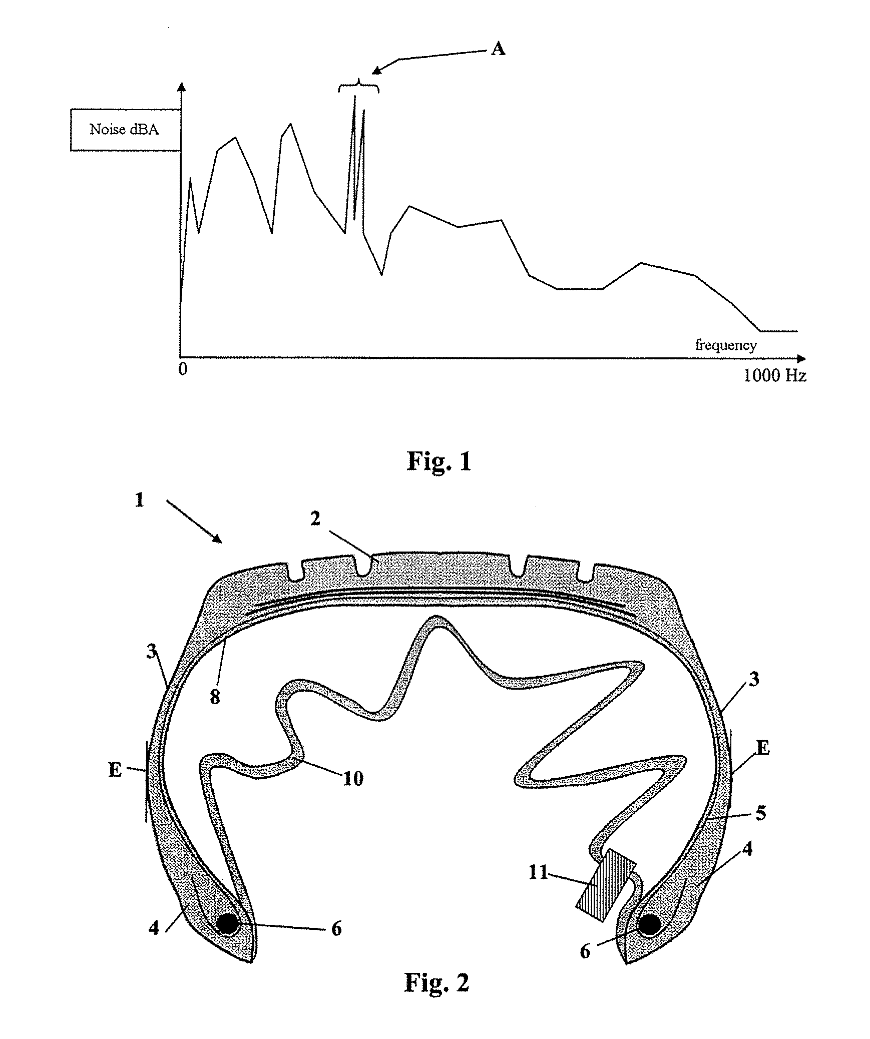
[0051]FIG. 1 presents a typical spectrum of noise amplitude as a function of frequency measured in a passenger vehicle traveling at 80 km / h. Two peaks, linked to a first cavity mode around 230 Hz (arrow A), are particularly noted. These two peaks are very audible and are a great nuisance from the point of view of comfort for the driver or a passenger of the vehicle.

[0052]FIG. 2 presents a tire 1 according to an embodiment of the invention seen in a partial axial cross section. The tire includes a tire structure formed of at least a crown 2 and two sidewalls 3 extended by two beads 4. A carcass-type reinforcing structure 5 is anchored into the two beads 4...


PUM

PropertyMeasurementUnit
Temperatureaaaaaaaaaa
Thicknessaaaaaaaaaa
Thicknessaaaaaaaaaa

Abstract

A tire with reduced rolling noise includes a tire structure formed of at least one crown extended by two sidewalls and two beads. A base of each of the two beads is configured to be mounted onto a rim seat. The tire also includes a carcass-type reinforcing structure anchored into the two beads and an additional layer bonded to an inner wall of the tire structure. The additional layer is bonded to the tire structure at its edges and the rest of the additional layer is not bonded. The additional layer includes an inflation valve.

Description

FIELD OF THE INVENTION[0001]The invention relates to a tire whose rolling noise within a vehicle is reduced so as to give improved comfort.BACKGROUND[0002]Many different noises pollute the environment of a vehicle. Some are due to the tires. In this type of noise, one part of the noise spectrum that is of particular nuisance is the cavity mode. The cavity mode is the resonance of the column of air inside the tire.[0003]The frequency range of the interior noise in a vehicle, which results from a tire when traveling, typically is 80 to 500 Hz. The frequency of the cavity mode is a function of the size of the tire. At very low speed, a peak in the first cavity mode (FCM) is around 230 Hz.[0004]When traveling, two peaks appear. At 80 km / h, the frequencies of these peaks are approximately 210 and 250 Hz. FIG. 1 clearly shows these frequencies (arrow A). From a subjective point of view of comfort, the peaks in the FCM are a nuisance as they are very audible.[0005]It is known that placing ...

Claims


Application Information

Patent Timeline
IPC IPC(8): B60C5/22B29C35/00B29C73/16
CPCB29D30/0061B29D2030/0687B60C19/002Y10T152/10495B60C5/025Y10T152/10603Y10T152/10522B60C19/122
Inventor MERINO-LOPEZ, JOSEBESTGEN, LUC
Owner MICHELIN & CO CIE GEN DES ESTAB MICHELIN
Learn More