Casting delivery nozzle with insert

a delivery nozzle and insert technology, applied in the direction of transportation and packaging, manufacturing tools, liquid transfer devices, etc., can solve the problems of premature solidification of molten metal, surface defects, microcracking of thin cast strips, etc., to reduce turbulence in flow, reduce splashing, and be relatively inexpensive

Inactive Publication Date: 2008-10-30
NUCOR CORP
View PDF27 Cites 29 Cited by
  • Summary
  • Abstract
  • Description
  • Claims
  • Application Information

AI Technical Summary

Benefits of technology

[0031]In each embodiment of both the improved delivery nozzle and method of casting steel strip with the delivery nozzle, each segment of the delivery nozzle is provided with a nozzle insert that assists in absorbing the kinetic energy of the molten metal entering the inner trough of the segments of the delivery nozzle, assists in protecting the passageways of the segments of the delivery nozzle from the impact of the molten metal, inhibits splashing and reduces turbulence in the flow of molten metal through the nozzle, and is relatively inexpensive and can be easily replaced. In addition, the inner trough dissipates a substantial part of the kinetic energy present in the molten metal by reason of downward movement through the metal delivery system from the tundish to the metal distributor to the delivery nozzle. The combination of the nozzle insert and inner trough through the passages to the side outlets further reduces the kinetic energy in the molten metal before reaching the casting pool. As a result, a more uniform and more quiescent flow of molten metal is provided to the casting pool to enhance uniform formation of the cast strip.
[0032]The nozzle insert also may be replaceable to further extend the useful life of the delivery nozzle.

Problems solved by technology

In prior art metal delivery nozzles, there has been a tendency to produce thin cast strip that contains surface defects and associated microcracking from uneven solidification at the chilled casting surfaces of the rolls.
By testing, we have found that a major cause of such defects is premature solidification of molten metal in the regions where the casting pool meets the casting surfaces of the rolls, generally known as the “meniscus” or “meniscus regions” of the casting pool.
In these regions, if solidification occurs before the molten metal has made contact with the roll surface, irregular initial heat transfer can occur between the metal shell and the casting rolls, resulting in formation of surface defects, such as depressions, ripple marks, cold shuts and / or microcracks.
If the temperature of the molten metal at the pool surface in the region of the meniscus becomes too low then surface cracks and “meniscus marks” (i.e., marks on the strip caused by the meniscus freezing while the pool level is uneven) are likely to occur
This localized heat loss near the side dams has a tendency to form “skulls” of solid metal in that region, which can grow to a considerable size and fall between the casting rolls and causing defects in the cast strip.
The flow of molten metal into the casting pool was improved; however, unevenness in metal flow adjacent the casting roll surfaces still tended to cause surface defects and surface cracks in the cast strip.
Further, there remained concern for wear on the delivery nozzle caused by the impact of the molten metal due to ferrostatic pressure, and turbulence caused as the molten metal moved through the delivery nozzle to discharge laterally into the casting pool below the meniscus of the casting pool.
In addition, the inner trough dissipates a substantial part of the kinetic energy present in the molten metal by reason of downward movement through the metal delivery system from the tundish to the metal distributor to the delivery nozzle.
The combination of the nozzle insert and inner trough through the passages to the side outlets further reduces the kinetic energy in the molten metal before reaching the casting pool.

Method used


Image

  • Casting delivery nozzle with insert
  • Casting delivery nozzle with insert
  • Casting delivery nozzle with insert

Examples


Embodiment Construction

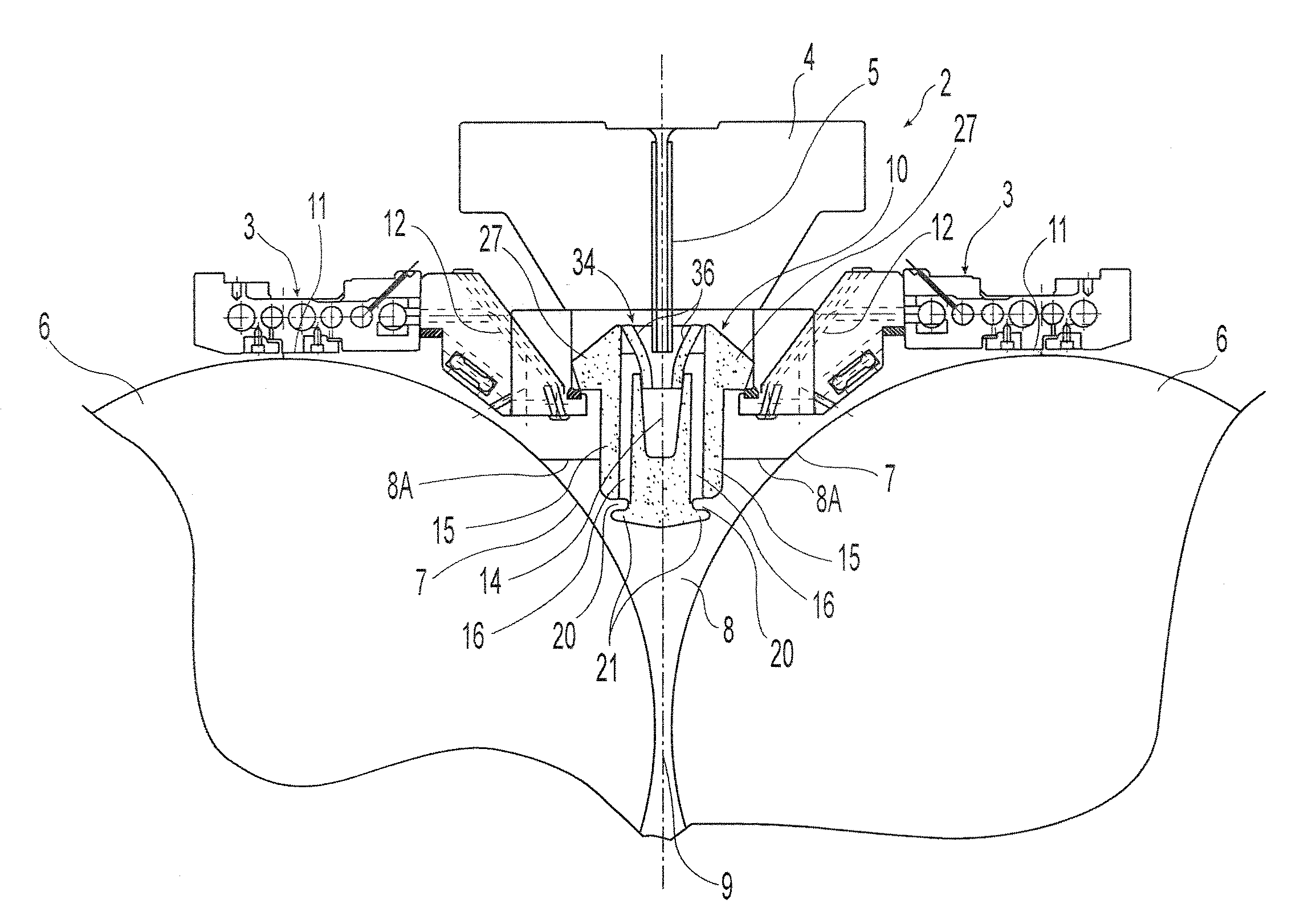
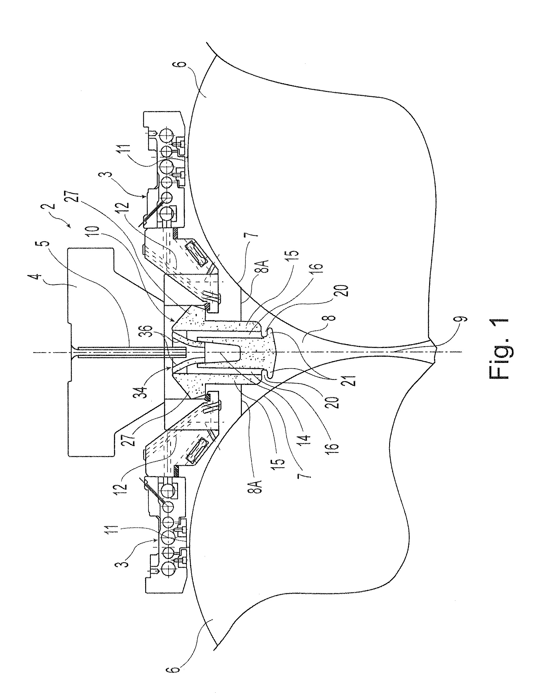
[0053]Referring to FIG. 1, the metal strip casting apparatus 2 includes a metal delivery nozzle 10 formed in segments 13 located below a metal distributor 4 (also called a moveable tundish or transition piece) and above casting rolls 6. Casting rolls 6 are laterally positioned with nip 9 formed between them. Metal distributor 4 receives metal from a ladle through a metal delivery system (not shown) and delivers the molten metal to delivery nozzle 10. A shroud 5 may extend from metal distributor 4 and into delivery nozzle 10, for the purpose of transferring molten metal into the segments of delivery nozzle 10. In the alternative, metal distributor 4 may transfer metal to the segments of delivery nozzle 10 via a hole in the bottom of metal distributor 4. Below delivery nozzle 10, a casting pool 8 having surface 8A is formed supported on the casting surfaces 7 of casting rolls 6 adjacent nip 9. Casting pool 8 is constrained at the ends of the casting rolls by side dams or plates (not s...


PUM

PropertyMeasurementUnit
temperatureaaaaaaaaaa
surface defectsaaaaaaaaaa
rate of heat lossaaaaaaaaaa

Abstract

A metal strip casting apparatus and a method of casting continuous metal strip includes assembling a pair of counter-rotatable casting rolls having casting surfaces positioned laterally forming a nip between for casting, and delivering molten metal through a delivery nozzle disposed above the nip capable to form a casting pool supported on the casting rolls. The delivery nozzle comprises segments each having elongate nozzle body with longitudinally extending side walls, end walls and a bottom part to form an inner trough, a nozzle insert disposed above bottom portions of the inner trough of each segment and supported relative to the nozzle body through which incoming molten metal may be delivered to the inner trough of each segment of the delivery nozzle, and the elongate nozzle body of each segment having passageways in fluid communication with the inner trough and outlet openings capable of discharging molten metal from the nozzle body outwardly into the casting pool.

Description

CROSS-REFERENCE TO RELATED APPLICATIONS[0001]This application is a continuation-in-part of U.S. patent application Ser. No. 12 / 013,791, filed Jan. 14, 2008, which claims priority from U.S. Provisional Application No. 60 / 885,778, filed Jan. 19, 2007. The disclosures of both applications are incorporated herein by reference.BACKGROUND AND SUMMARY[0002]This invention relates to making thin strip and more particularly casting of thin strip by a twin roll caster.[0003]It is known to cast metal strip by continuous casting in a twin roll caster. Molten metal is introduced between a pair of counter-rotating horizontal casting rolls which are cooled so that metal shells solidify on the moving roll surfaces, and are brought together at the nip between them to produce a solidified strip product delivered downwardly from the nip between the rolls. The term “nip” is used herein to refer to the general region at which the rolls are closest together. The molten metal may be poured from a ladle int...

Claims


Application Information

Patent Timeline
Patent Type & Authority Applications(United States)
IPC IPC(8): B22D11/06B22D45/00
CPCB22D11/0642
Inventor BLEJDE, WALTER N.SCHUEREN, MIKESOSINSKY, DAVID J.WHITE, BRIAN D.SCHLICHTING, MARK
Owner NUCOR CORP
Why Eureka
Try Eureka