Brake System Fault Pedal Gain Change Method and System

a technology of fault pedal and gain change, which is applied in the direction of braking components, process and machine control, force/torque/work measurement apparatus, etc., can solve the problems of pressure generation device or pump to fault or fail to activate, and achieve the effect of abruptly reducing the performance of the braking system

Active Publication Date: 2008-10-30
GM GLOBAL TECH OPERATIONS LLC
View PDF21 Cites 33 Cited by
  • Summary
  • Abstract
  • Description
  • Claims
  • Application Information

AI Technical Summary

Benefits of technology

[0012]According to one aspect of the present invention, the gradual brake system degradation apparent to the driver alerts the driver to a serious brake system fault by providing tactile feedback to the driver in the form of an increase in brake pedal force required to decelerate or stop the vehicle. The present invention brings about a gradual decrease in braking system performance over time rather than the abrupt drop in brake system performance that would occur when the brake boost system is no longer able to assist the driver in stopping the vehicle as would occur without the present invention. This gradual decrease in brake performance mimics the response to a fault in mechanical brake systems which a driver can logically associate with a vehicle brake system problem.
[0013]According to the present invention, in the event of a brake system fault such as a pump motor fault, a multiplier (also known as a reduction calibration) is applied to the driver requested brake torque which will reduce the total requested driver braking torque (as sensed from the applied brake pedal force and / or travel) by a calibrated percentage. It is important that the calibrated percentage reduction allow the vehicle to continue to meet FMVSS-135 guidelines during the fault. The driver is alerted to the detected fault by the resultant effect that a slightly higher pedal force is then required to achieve a given deceleration.

Problems solved by technology

It is possible for the pressure generating device or pump to fault or fail to activate during vehicle operation.

Method used


Image

  • Brake System Fault Pedal Gain Change Method and System
  • Brake System Fault Pedal Gain Change Method and System
  • Brake System Fault Pedal Gain Change Method and System

Examples


Embodiment Construction

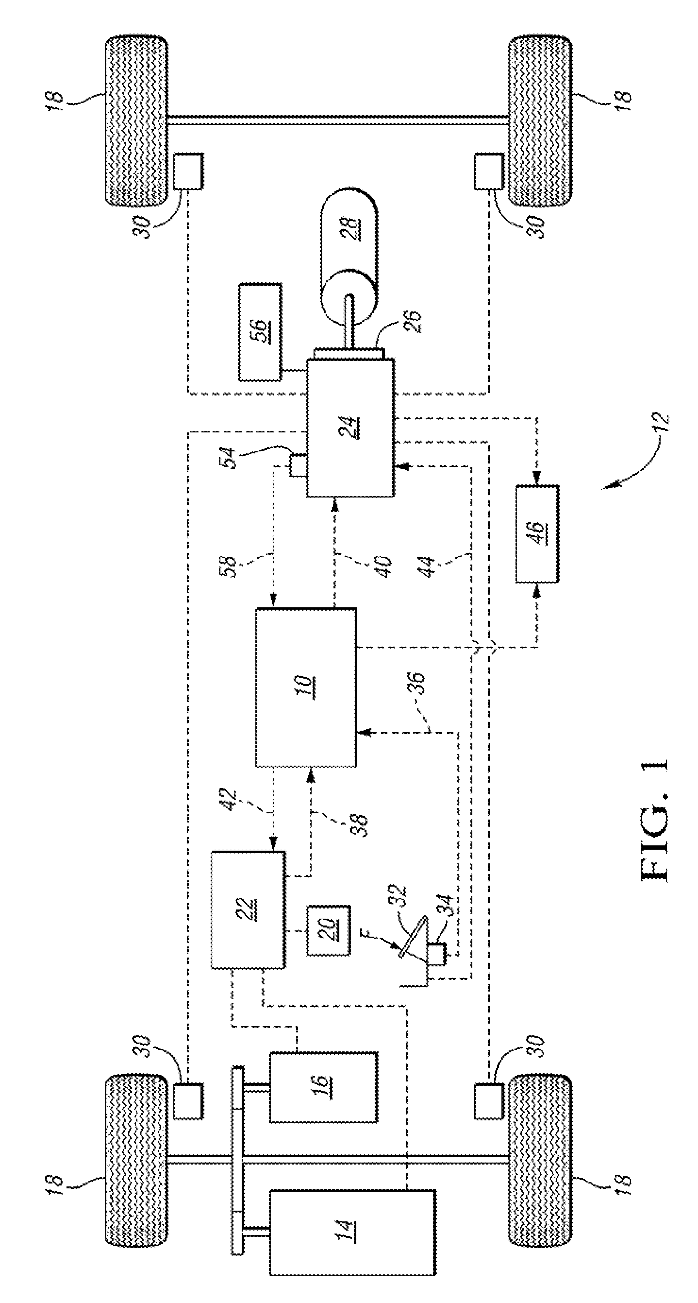
[0022]FIG. 1 is a schematic representation of a hybrid vehicle 12 equipped with a controller or brake simulator 10 implementing a brake system fault pedal gain change method consistent with the present invention. The hybrid vehicle 12 is mechanically propelled by either the engine 14 or the motor / generator 16. The electric drive control 22 regulates the operation of the motor / generator 16, controlling the operating mode of the motor generator 16. When the motor / generator 16 is operating to electrically propel the hybrid vehicle 12, the motor / generator 16 draws electrical power from the battery 20 through the electric drive control 22. Alternately the motor / generator 16 may operate as a generator to provide a regenerative brake torque to decelerate the hybrid vehicle 12 by converting a portion of the kinetic energy due to the rolling motion of the vehicle 12 into electrical energy which is stored to the battery 20 through the electric drive control 22. The hybrid vehicle 12 includes ...


PUM

PropertyMeasurementUnit
brake pedal forceaaaaaaaaaa
brake torqueaaaaaaaaaa
torqueaaaaaaaaaa

Abstract

A brake system fault pedal gain change method and system for brake pedal simulator equipped vehicles such as hybrid electric vehicles is provided. In the event of a brake system booster fault, the method alerts the driver by way of tactile feedback. Additionally, the disclosed method provides a controlled means to gradually increase required brake pedal force during a brake system fault to avoid an abrupt change in brake pedal force when the brake system boost is depleted.

Description

TECHNICAL FIELD[0001]The present invention provides brake system fault pedal gain change method and system for brake pedal simulator equipped vehicles, providing feedback to a driver in the form of an increase in the amount of brake pedal actuation force required to achieve a given vehicle deceleration so as to warn the driver of a detected fault in the vehicle brake boost system.BACKGROUND OF THE INVENTION[0002]Brake systems are critical to the safe operation and control of a motor vehicle. In conventional vehicle brake systems, the vehicle driver depresses the brake pedal to decelerate the vehicle and the vehicle brake system responds with a reactive force back to the driver through the pedal that the driver may mentally relate to the amount of braking torque applied by the vehicle braking system. In a hydraulic boosted or assisted braking system, as the driver depresses the brake pedal the booster device generates a brake line pressure corresponding to a multiple (also known as b...

Claims


Application Information

Patent Timeline
Patent Type & Authority Applications(United States)
IPC IPC(8): B60T13/66B60T13/74F16D65/36G06G5/00G01L5/28B60T13/00F16D65/28
CPCB60T7/06B60T13/586B60T17/18
Inventor KARNJATE, TIMOTHY M.MANOSH, WILLIAM K.
Owner GM GLOBAL TECH OPERATIONS LLC
Why Eureka
Try Eureka