Light source module

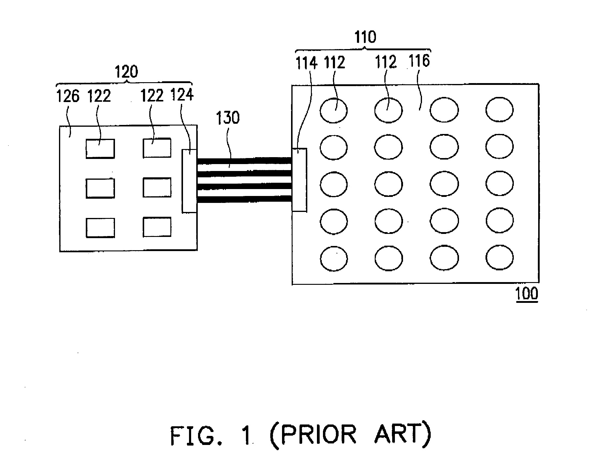
a technology of light source module and back light module, which is applied in the direction of semiconductor devices for light source, lighting and heating apparatus, planar light source, etc., can solve the problems of prolonged assembling time, increased manufacturing cost of back light module b>100/b>, and complicated assembling process, etc., and achieves short assembling time and low manufacturing cost

Inactive Publication Date: 2008-10-30
CHUNGHWA PICTURE TUBES LTD
View PDF8 Cites 13 Cited by
  • Summary
  • Abstract
  • Description
  • Claims
  • Application Information

AI Technical Summary

Benefits of technology

[0009]The present invention is directed to a light source module with the characteristics of a low manufacturing cost and short assembling time.
[0016]In view of the aforementioned, the plurality of driving devices and the plurality of light emitting chip packages are assembled on the same circuit substrate in the light source module of the invention, so that the number of components in the light source module is reduced so as to lower the manufacturing cost. Meanwhile, the assembling process of the light source module in the invention is simplified so as to shorten the assembling time as well.

Problems solved by technology

However, since the back light module 100 includes additional components such as the first PCB 116, the second PCB 126, the first connector 114, the second connector 124 and the cable 130, not only the manufacturing cost of the back light module 100 is increased, but also the assembling process is rendered overly complicated such that the assembling time is prolonged.

Method used


Image

  • Light source module
  • Light source module
  • Light source module

Examples


Embodiment Construction

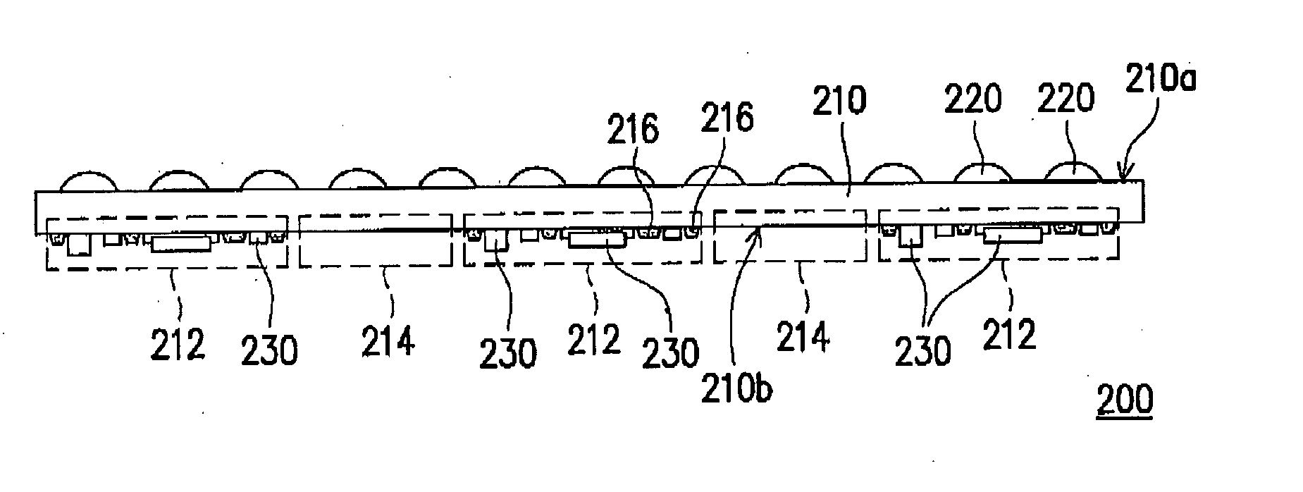
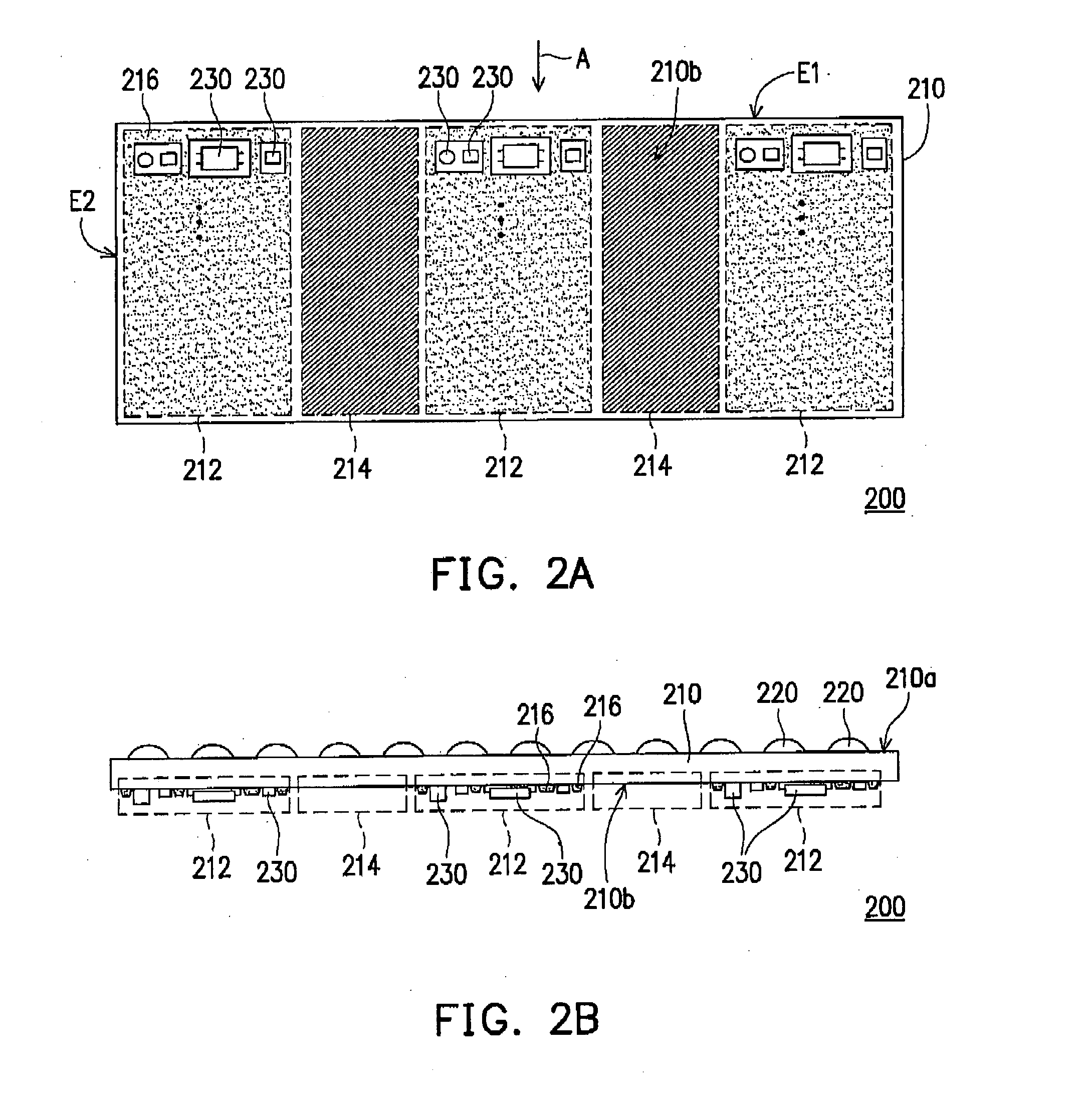
[0024]FIG. 2A is a schematic bottom view of the light source module according to the first embodiment of the present invention. FIG. 2B is a schematic side view of the light source module of FIG. 2A along a direction A. Referring to FIGS. 2A and 2B, a light source module 200 includes a circuit substrate 210, a plurality of light emitting chip packages 220 and a plurality of driving devices 230. The light source module 200 can be used as a back light module in a display or a light source module for other lighting purposes.

[0025]The circuit substrate 210 has a top surface 210a and a bottom surface 210b. The bottom surface 210b is opposite to the top surface 210a. The bottom surface 210b has at least one component installed area 212 and at least one metal exposed area 214. Although the circuit substrate 210 illustrated in FIG. 2A has three component installed areas 212 and two metal exposed areas 214, the numbers of the component installed areas 212 and the metal exposed areas 214 only...


PUM


Abstract

A light source module including a circuit substrate, light emitting chip packages, and driving devices is provided. The circuit substrate has a top surface and a bottom surface opposite to the top surface. The bottom surface has at least one component installed area and at least one metal exposed area. The light emitting chip packages are disposed on the top surface. The driving devices are disposed in the component installed area. The driving devices are electrically connected to the light emitting chip packages through the circuit substrate.

Description

CROSS-REFERENCE TO RELATED APPLICATION[0001]This application claims the priority benefit of Taiwan application serial no. 96114735, filed Apr. 26, 2007. All disclosure of the Taiwan application is incorporated herein by reference.BACKGROUND OF THE INVENTION[0002]1. Field of the Invention[0003]The present invention relates to a light source module, and more particularly to a light source module adopting light emitting chip packages.[0004]2. Description of Related Art[0005]With progress in the technology, nowadays, the light emitting diode (LED) has the advantages of high luminance, low driving voltage and fast driving speed. Therefore, LEDs have already been adopted as the light source of the back light module in some liquid crystal displays (LCDs).[0006]FIG. 1 is a schematic top view of a conventional back light module adopting an LED as its light source. Referring to FIG. 1, a back light module 100 includes an LED module board 110, a driver board 120 and a cable 130. The LED module...

Claims


Application Information

Patent Timeline
Patent Type & Authority Applications(United States)
IPC IPC(8): H01J7/24H05B37/00
CPCF21K9/00H05K1/0209H05K1/181H05K2201/066H05K2201/09781H05K2201/09972H05K2201/10106H05K2203/1572F21V23/005F21Y2101/02F21Y2105/008F21Y2105/00F21Y2115/10F21Y2115/15
Inventor LIN, SHIN-CHANGCHEN, BI-HSIENCHAO, HAN-YU
Owner CHUNGHWA PICTURE TUBES LTD
Why Eureka
Try Eureka