Proximity detector and proximity detecting method

a detector and proximity technology, applied in the direction of resistance/reactance/impedence, pulse technique, instruments, etc., can solve the problems of difficult detection of difference in capacitance, difficult to obtain exact stray capacitance by charging or discharging electrodes, and difficult to achieve high response speed, the effect of stable detection

Inactive Publication Date: 2008-10-30
RPX CORP
View PDF13 Cites 63 Cited by
  • Summary
  • Abstract
  • Description
  • Claims
  • Application Information

AI Technical Summary

Benefits of technology

[0024]According to the present invention, even when the proximity detector is close to a noise source or a thickness of a cover of the proximity detector is large, the proximity detector and the proximity detecting method, which permit a stable detection at a high response speed, can be realized.

Problems solved by technology

It is, however, difficult to obtain an exact stray capacitance by charging or discharging the electrode only once since an increase in stray capacitance of the electrode, which is caused by the approach of a human or the like, is as small as around 1 pF.
According to the conventional method as described above, however, a highly accurate detection is difficult because the increase in stray capacitance caused by the approach of the object is small as compared with the stray capacitance of the electrode itself.
Accordingly, a difference in capacitance becomes difficult to detect.
On the other hand, it is difficult to reduce the noise since separate placement of each differential electrode of the pair causes different degree of noise to affect the electrodes.
According to any one of the methods, a small stray capacitance of the electrode results in a high impedance.
As a result, the detected stray capacitance is susceptible to noise or the like.
In particular, when transparent support and electrodes are provided on a display face of a display device such as a liquid crystal display device, the proximity detector is greatly affected by the noise from the display device because the proximity detector is close to the display device.
However, because the change in the signal from the display device is not the one and only source of the noise generation, the method does not necessarily provide a satisfactory solution.
Accordingly, a distance between the proximity detector and the display device is increased to adversely increase a thickness of the entire device, or a thickness of a cover of the proximity detector cannot be sufficiently increased.
As described above, the conventional proximity detectors and proximity detecting methods have problems such as a large detection error, a response speed lowered for eliminating the effects of noise, the need of increasing a distance from a noise source for providing the proximity detector, and the need of reducing a thickness of the cover of the proximity detector.

Method used


Image

  • Proximity detector and proximity detecting method
  • Proximity detector and proximity detecting method
  • Proximity detector and proximity detecting method

Examples


embodiment 1

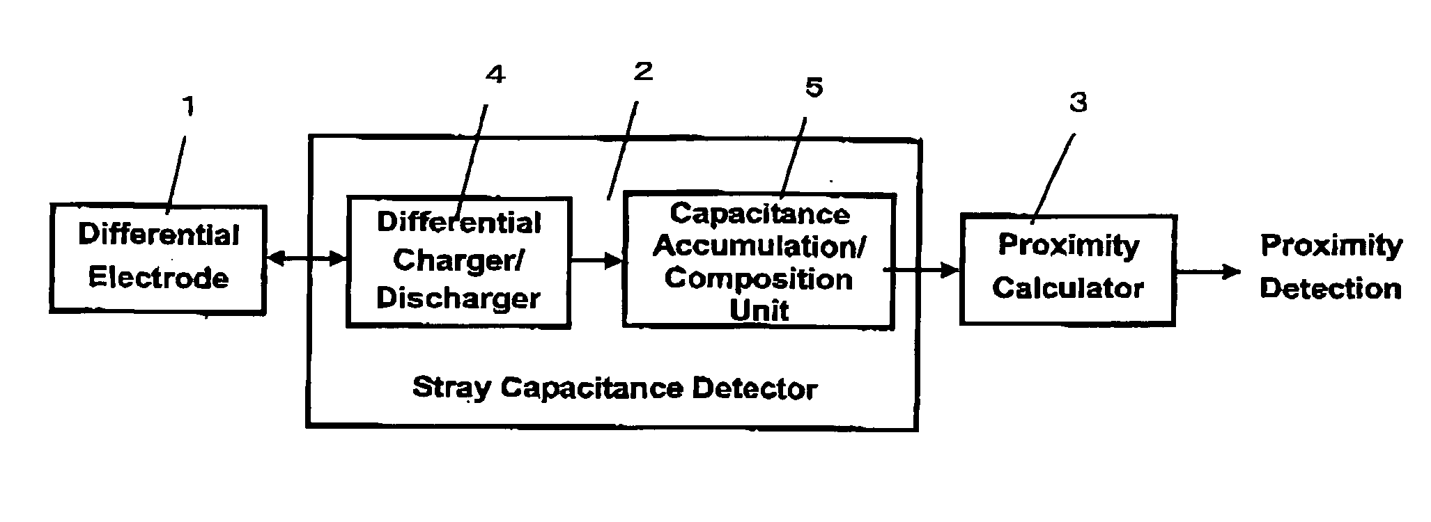
[0060]A preferred embodiment of the present invention will be described referring to FIG. 1.

[0061]A proximity detector according to the present invention includes a differential electrode for detecting approach of an object as a change in stray capacitance, a stray capacitance detector for obtaining a composite value of apparent stray capacitances of the differential electrode, and proximity calculator for detecting the approach of the object supposed from the composite value of the stray capacitances. The stray capacitance detector includes a differential charger / discharger for repeatedly charging and discharging the differential electrode, and capacitance accumulation / composition unit for accumulating a characteristic of the charge and discharge repeated by the differential charger / discharger for the differential electrode to obtain the composite value of the apparent stray capacitances of the differential electrode.

[0062]Hereinafter, each constituent in the proximity detector acc...

second embodiment

[0115]In the first embodiment, the proximity detector including the single differential electrode to detect the approach of the object has been described. In the second embodiment a proximity detector which is able to detect not only the approach of the object but also the position of the object by the use of a plurality of differential electrodes will be described.

[0116]For this purpose, in the second embodiment, as illustrated in FIG. 24, the proximity detector includes a plurality of the differential electrodes 1 supported by support 61, the stray capacitance detector 2 for detecting each of the stray capacitances of the plurality of differential electrodes, and the proximity calculator 3 for computing the approach and the position of the object based on the positions of the plurality of differential electrodes and each of the stray capacitances of the plurality of differential electrodes obtained by the stray capacitance detector 2.

[0117]Hereinafter, each constituent component w...

third embodiment

[0142]In the second embodiment, the proximity detector for obtaining the composite capacitance of the positive element electrode and the negative element electrode of the differential electrode from the characteristic of the differential charge / discharge to detect the stray capacitance with the noise being removed to accurately detect the approach and the position of the object has been described. In such a case, however, one pair of the positive element electrode and the negative element electrode of the differential electrode is required to obtain the electrostatic capacitance for one position. Accordingly, the number of required electrodes is doubled as compared to a conventional simple measurement of the stray capacitance, resulting in increase of the detection circuit scale.

[0143]Thus, in the third embodiment, a proximity detector for obtaining the electrostatic capacitance of each of the closely arranged electrodes constituting the differential electrode, while removing the no...


PUM


Abstract

A differential electrode is charged and discharged in the opposite phases. By obtaining the sum of stray capacitances of the differential electrode from charge/discharge characteristics, the approach or the position of an object is detected based on the stray capacitances from which noise is cancelled.

Description

BACKGROUND OF THE INVENTION[0001]1. Field of the Invention[0002]The present invention relates to a proximity detector and a proximity detecting method for detecting the approach and the position of an object such as a human finger based on a stray capacitance corresponding to an electrostatic capacitance intrinsic to the object.[0003]2. Description of the Related Art[0004]It is known that an apparent stray capacitance of an electrode increases when an object having a stray capacitance such as a human approaches the electrode. The application of this principle puts a proximity detector such as an electrostatic touch sensor into practical use.[0005]In order to detect the stray capacitance of the electrode, the proximity detector as described above obtains the apparent stray capacitance of the electrode from the relation between a voltage and electric charges during charge or discharge of the electrode. It is, however, difficult to obtain an exact stray capacitance by charging or disch...

Claims


Application Information

Patent Timeline
Patent Type & Authority Applications(United States)
IPC IPC(8): G01B7/14
CPCH03K17/962H03K2017/9602H03K2017/9613H03K2217/94026H03K2217/960705H03K2217/960725H03K2217/960755G01D5/24H03K17/955H03K17/9622
Inventor MATSUSHIMA, KENICHI
Owner RPX CORP
Why Eureka
Try Eureka