Distance Measuring Device and Method for Testing the Operation of a Distance Measuring System

a technology of distance measurement and distance measurement device, which is applied in the direction of testing/monitoring control system, program control, instruments, etc., can solve the problems of inability to detect obstacles in the long-range measuring system, measurement may be impaired, and the entire area in front of the vehicle cannot be detected, so as to achieve the maximum possible angular coverage, reduce the effect of angular coverage and high degree of reliability of measured results

Inactive Publication Date: 2008-10-30
ROBERT BOSCH GMBH
View PDF5 Cites 39 Cited by
  • Summary
  • Abstract
  • Description
  • Claims
  • Application Information

AI Technical Summary

Benefits of technology

[0003]The distance measuring device according to the present invention and the method for testing the operation of a distance measuring system according to the present invention have the advantage over the related art that a distance measuring system which is operated using a second measuring method is tested using a distance measuring system which is operated using a first measuring method. Different measuring methods are to be understood here as different physical principles using which a distance measurement is performed. Thus, for example, acoustic distance measurement, e.g., ultrasonic distance measurement, and electromagnetic distance measurement, e.g., radar distance measurement or infrared light distance measurement (LIDAR), are based on different physical principles. In that case, in one instance the propagation and propagation time of sound waves and in one instance the propagation time of electromagnetic waves are used for a measurement. Should one measuring method be impaired, this will not generally impact the other measuring method. For example, in the event of an electromagnetic interference, the propagation of sound waves does not need to be affected. If, on the contrary, ultrasonic sensors are contaminated, such a contamination, if it also occurs at all in front of a radar sensor, will only negligibly impair the propagation of radar beams or will not impair the propagation at all. In contrast to a pure self-test, monitoring of the second measuring system by the first measuring system, which operates according to a different measuring method, ensures a high degree of reliability of the measured results. Reliable and virtually interference-free information may thus be obtained about the operation of a measuring system in the vehicle.
[0004]It is particularly advantageous that the first measuring system is designed as a measuring system having a long range and the second measuring system as a measuring system having a short range and a maximum possible angular coverage. While the long-range measuring system may cover a remote area on the road in front of the vehicle, the measuring system having wide angular coverage is used in particular for covering, if possible, the entire surroundings of the vehicle, at least in an area in front of the vehicle or behind the vehicle in the direction of travel, so that possibly no blind spot exists in the direction of travel. If there is an obstacle directly in front of the vehicle at a distance that may be monitored by both measuring systems, both systems are in a position to detect the obstacle. An overlapping area of coverage by both systems thus exists in the close range. In such a case, the systems may mutually test the operation of one another. In particular, the short-range system may be tested if the long-range system detects an obstacle in the closer surroundings of the vehicle within the range of the short-range system. If such an obstacle exists and is detected by the long-range system, the short-range system must also be able to detect this obstacle in the close range. It is advantageous in particular if the short-range system is designed as an ultrasonic distance measuring device and the long-range system is designed as a radar distance measuring device or infrared distance measuring device.
[0005]It is furthermore advantageous if the operating test is performed shortly before starting the vehicle to ensure that both systems are operational at start. Obstacles such as pedestrians are thus reliably detected by a distance measuring device and the driver may be warned about such an obstacle. In particular if there is a long-range measuring system, this system is primarily intended for detecting obstacles at a longer distance of 10 m to 200 m, for example. In the close range, for example, between 1 m and 10 m, distance measurement is also possible, but the entire area in front of the vehicle cannot be detected due to a possibly reduced angular coverage. If there is an obstacle in this close range in front of the vehicle, this obstacle may not be detected by the long-range measuring system. However, the short-range measuring system is able to detect this obstacle. Such a warning may, however, be output by the short-range measuring system with a high degree of reliability only if its operation has been tested. For example, if snow or sleet has deposited on the short-range measuring system during travel, the measurement may be impaired, in particular if sound signals are used for the measurement. The obstacle in front of the vehicle would then be seen neither by the long-range system nor by the short-range system. However, if an obstacle in front of the vehicle is within a distance that allows obstacle detection for both the long-range and short-range systems, both systems must detect the obstacle. An operating test advantageously takes place in that, in the event where the long-range measuring system detects the obstacle, an attempt is made to also measure the distance to the obstacle using the short-range measuring system. If in this case the short-range measuring system also detects the obstacle, the operation of the short-range measuring system is ensured. If it does not detect the obstacle, obstacle monitoring in the area in front of the vehicle may not be reliably performed prior to start. A particularly reliable operating test of the short-range system may be advantageously performed if the long-range system has detected an obstacle stopping in front of it, because obstacle detection is particularly reliable in the case of moving objects due to the design of the system.
[0006]It is advantageous in particular if the monitoring measurement is performed shortly before the vehicle starts moving again. An intent to start moving may be detected, for example, by a gear having been engaged or selected, the brake having been released, or the gas pedal having been touched. This ensures that when the vehicle subsequently starts moving, the travel area in front of the vehicle is being effectively monitored and the driver may be warned about an obstacle if necessary.
[0007]It is furthermore advantageous if an appropriate measurement is provided in a vehicle, which automatically resumes travel after stopping only if the vehicle traveling ahead also starts moving again. In that case, if the vehicle is stopped, pedestrians may use the opportunity to cross the street, for example, and be in the time period between the front vehicle and the host vehicle when the front vehicle starts moving. If no reliable obstacle detection takes place, the host vehicle may start and put the pedestrian that is between the moving front vehicle and the following host vehicle at risk. However, in the event of reliable obstacle detection this risk may be ruled out.

Problems solved by technology

In the close range, for example, between 1 m and 10 m, distance measurement is also possible, but the entire area in front of the vehicle cannot be detected due to a possibly reduced angular coverage.
If there is an obstacle in this close range in front of the vehicle, this obstacle may not be detected by the long-range measuring system.
For example, if snow or sleet has deposited on the short-range measuring system during travel, the measurement may be impaired, in particular if sound signals are used for the measurement.
However, if an obstacle in front of the vehicle is within a distance that allows obstacle detection for both the long-range and short-range systems, both systems must detect the obstacle.
If it does not detect the obstacle, obstacle monitoring in the area in front of the vehicle may not be reliably performed prior to start.

Method used


Image

  • Distance Measuring Device and Method for Testing the Operation of a Distance Measuring System
  • Distance Measuring Device and Method for Testing the Operation of a Distance Measuring System
  • Distance Measuring Device and Method for Testing the Operation of a Distance Measuring System

Examples


Embodiment Construction

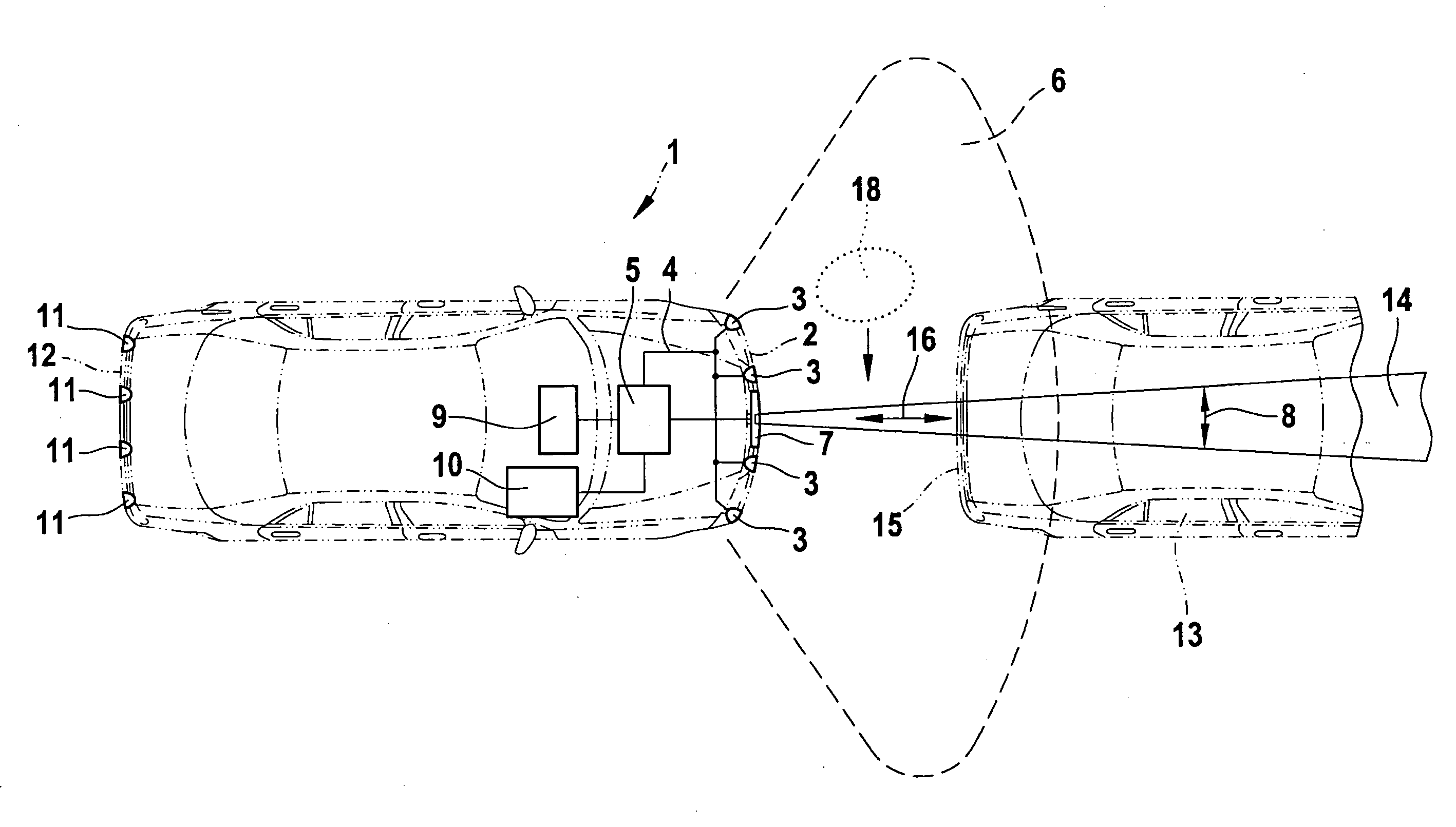
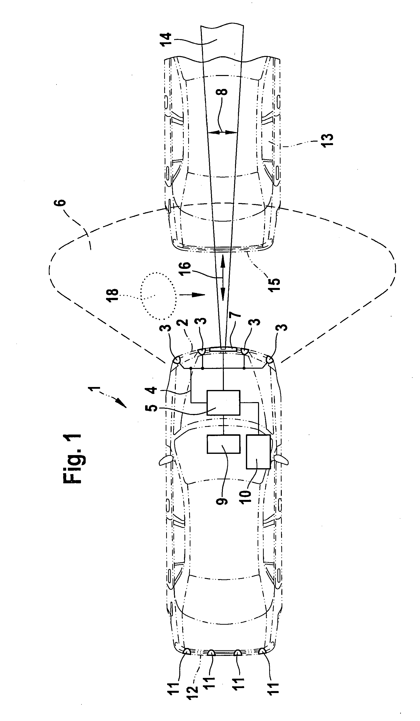
[0010]The present invention may be used for any desired distance measuring device that has at least two measuring systems operating by different measuring methods. The physical principles by which the measuring systems operate should be different. One measuring system may be an ultrasonic distance measuring system, for example. Another measuring system may be an infrared system which has two or more wide-angle sensors. A video distance measuring system having a camera analyzer, a LIDAR distance measuring system, a radar distance measuring system, or an acoustic distance measuring system may also be used as different measuring methods. It is advantageous, for example, if at least one ultrasonic distance measuring system and one radar distance measuring system are integrated in a distance measuring device of a vehicle. Therefore, the present invention is elucidated in the following on the basis of the example of such a distance measuring device.

[0011]A vehicle 1 having a distance meas...


PUM


Abstract

A distance measuring device for measuring a distance of a vehicle to an obstacle and a method for testing the operation of a distance measuring system. Two measuring systems are provided, each operating according to a different measuring method. Reliable operation of the second measuring system is established when the second measuring system detects an obstacle which has already been detected by the first measuring system.

Description

BACKGROUND INFORMATION[0001]Distance measuring devices for motor vehicles which use ultrasonic signals to determine the distance to obstacles in the surroundings of the vehicle are known. An ultrasonic signal is emitted by a sensor, and the signal is reflected by an obstacle. The reflected signal is received again by the sensor that emitted it, or possibly also by another sensor. The distance of the obstacle to the vehicle is determined from the propagation time of the signal. Ultrasonic distance measuring devices of this type are used mostly for supporting the driver in parking the vehicle. These devices make use of the fact that the entire surroundings of the vehicle, but at least a wider angular range in front of and / or behind the vehicle, may be covered using relatively few sensors. In general, however, the range of ultrasonic sensors is limited. For other applications, for example, for adaptive cruise control (ACC), radar sensors are used, in which radar signals are emitted, re...

Claims


Application Information

Patent Timeline
Patent Type & Authority Applications(United States)
IPC IPC(8): H04Q9/00G01S13/931
CPCG01S7/4004G01S2013/9375G01S13/931G01S2013/9364G01S13/867G01S13/862G01S13/865G01S2007/4975G01S2007/4039G01S2013/9321G01S2013/9325G01S2013/9346G01S2013/935G01S2013/9353G01S7/52004G01S2013/9319G01S2013/93185G01S2013/932G01S2013/9324G01S2013/93271G01S7/4039
Inventor SCHMID, ROLAND
Owner ROBERT BOSCH GMBH
Why Eureka
Try Eureka